9
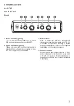
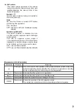
10. DIP switch
This switch allows selection of the device
being connected to Sub-Unit jack A (8), and
enables/disables the low-cut filter of the
Sub-Unit speaker.
• Switch 1
[ ]
Selects type of device being connected to
Sub-Unit jack A (8).
Note
Be sure the Power is turned OFF before
performing this operation.
ON: Headset
OFF: Sub-Unit or NF-CS1 Distributor (factory
default)
• Switch 2 [LOW CUT]
This switch enables or disables the low-
cut filter used to suppress low-to-midrange
sound output.
Turn ON to suppress sound output if
concerned about privacy or if the Sub-Unit is
installed in a location where sound is likely
to be muffled, such as near a wall or desk.
ON: Low-cut filter enabled
OFF: Low-cut filter disabled (factory default)
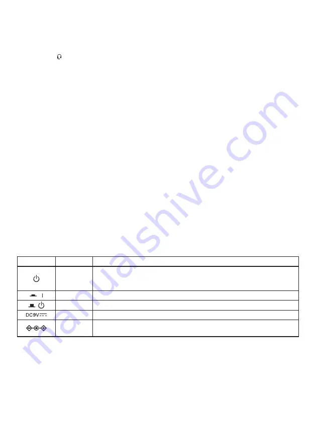
[Explanation of Unit Symbols]
Indication
Position
Meaning
Front panel The LED next to this symbol is the power indicator, which shows the
system’s operating status. Whether the system is in operation or standby
mode is indicated by the LED being lit or extinguished.
Rear panel Indicates that the system is in operation.
Rear panel Indicates that the system is in standby mode.
Rear panel Shows the system’s power voltage (9 V DC).
Rear panel Shows the polarity of the AC adapter socket.
The center pin is positive and its surrounding surface is negative.

