2-3
Chapter 2: UNIT AND SOFTWARE INSTALLATIONS
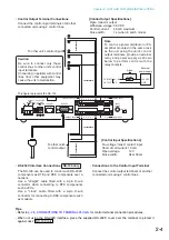
1.2. Terminal Connections
MIC
LINE
VOLUME
INPUT
24V
DC INPUT
AUDIO OUTPUT
FG
7
6
7
6
AUDIO INPUT
8 C
5
4
3
2
1
C
8
5
4
3
2
1
CONTACT OUTPUT
CONTACT INPUT
RS-232C
200mA
10/100M
H C E
H C E
AC ADAPTER
24V 200mA
DC INPUT
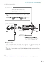
• Audio Input Terminal Connections
Connect the microphone or other sound
sources using 2-core shielded cable.
• Audio Output Terminal Connections
Connect the mixer, amplifier, etc. using 2-core
shielded cable.
• Network Connections
To microphone or
other sound sources
To mixer, amplifier, etc.
H C E
H C E
The NX-100/100S automatically distinguishes between 10BASE-T and 100BASE-TX networks, and
establishes a connection. For this connection, use a "straight" UTP Category 5 LAN (Ethernet) cable
fitted with an RJ-45 connector.
Tip
It is recommended that the unit be connected to network equipment capable of performing full-duplex
communications.
When the connected unit has an unbalanced input, make the connections
as follows:
NX-100/100S
Connected Unit
H
E
Hot (H)
Cold (C)
Earth (E)
Shield
Shield
This figure represents the NX-100.
Note
Refer to
Summary of Contents for NX-100
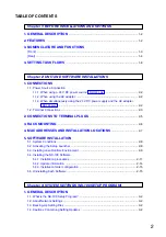
Page 6: ...Chapter 1 BEFORE INSTALLATIONS AND SETTINGS ...
Page 12: ...Chapter 2 UNIT AND SOFTWARE INSTALLATIONS ...
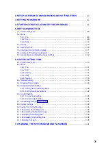
Page 27: ...Chapter 3 SYSTEM SETTINGS NX 100 SETUP PROGRAM ...
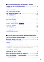
Page 58: ...Chapter 4 SYSTEM SETTINGS SETTING USING BROWSER ...
Page 89: ...Chapter 5 OPERATION SETTINGS NX 100 OPERATION PROGRAM ...
Page 104: ...Chapter 6 APPENDIX ...
Page 114: ...200708 URL http www toa jp ...

