2-4
Chapter 2: UNIT AND SOFTWARE INSTALLATIONS
MIC
LINE
VOLUME
INPUT
24V
DC INPUT
AUDIO OUTPUT
FG
7
6
7
6
AUDIO INPUT
8 C
5
4
3
2
1
C
8
5
4
3
2
1
CONTACT OUTPUT
CONTACT INPUT
RS-232C
200mA
10/100M
H C E
H C E
AC ADAPTER
24V 200mA
DC INPUT
7
6
8 C
5
4
2 3
1
7
6
C
8
5
4
3
2
1
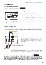
Open collector output
Withstand voltage: 30 V DC
Control current: 50 mA maximum
Pulse width: 1 s (when in Latch mode)
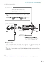
[Control Output Specifications]
To other unit's control input
• Control Output Terminal Connections
Connect the control input terminals of all other
connected units using 2 control lines.
Caution
Be sure to connect only these
control lines to other unit's control
input terminals.
Connecting in parallel with control
lines from other equipment may
cause the unit to malfunction.
This figure represents the NX-100.
CONTACT
OUTPUT
1 – 8
C
+24 V DC
External
power supply
Relay
Diode
GND
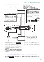
Note
To control a power distributor or PA
amplifier mounted in the same rack
as the unit using the unit's control
output terminals, provide an external
relay and power supply as shown
below to perform control with the
relay contacts.
No-voltage "make" contact input
Short circuit current: 10 mA
Open voltage: 12 V
Pulse width: Over 50 ms
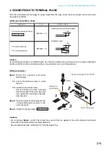
[Control Input Specifications]
To other unit's
control output
• Connections to the Control Input Terminal
Connect the control output terminals of all other
connected units using 2 control lines.
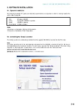
• RS-232C Interface Connections
The NX-100 can be used to control such RS-232C
components as DTE and DCE components over a
network.
Use a "straight" cable fitted with a 9-pin D-sub
connector when connecting to DTE components
such as PCs.
Use a "cross" cable fitted with a 9-pin D-sub
connector for connecting to DCE components such
as modems.
NX-100 only
Tips
• Refer to
p. 2-5, CONNECTIONS TO TERMINAL PLUGS
, for control terminal connection procedures.
• When not using the RS-232C interface, place the supplied RS-232C cover over the terminal to protect it
against dust. NX-100 only
Summary of Contents for NX-100
Page 6: ...Chapter 1 BEFORE INSTALLATIONS AND SETTINGS ...
Page 12: ...Chapter 2 UNIT AND SOFTWARE INSTALLATIONS ...
Page 27: ...Chapter 3 SYSTEM SETTINGS NX 100 SETUP PROGRAM ...
Page 58: ...Chapter 4 SYSTEM SETTINGS SETTING USING BROWSER ...
Page 89: ...Chapter 5 OPERATION SETTINGS NX 100 OPERATION PROGRAM ...
Page 104: ...Chapter 6 APPENDIX ...
Page 114: ...200708 URL http www toa jp ...

