background image

4-11

Chapter 4:  SYSTEM SETTINGS (SETTING USING BROWSER)

(3) Target Unit

The IP addresses of the target NX-100 and NX-100S units are displayed.
When "Transmission" is selected in the Direction setting, broadcasts are sent all added NX-100 and
NX-100S target units. 
When "Reception" is selected, broadcasts are received from the added target NX-100 or NX-100S unit.
Target units cannot be added when "Local" has been selected.

[Target Unit Addition]

The combination of the broadcast direction and target unit that enables single stream broadcasts can be
set as the broadcast pattern. The number of target units that can be added is 1 unit for reception, and 64
units for transmission when multicast streaming is possible or 1 unit for transmission when multicast
streaming is not possible. 
Enter the IP address and transmission control port for each target unit, then press the Target Unit Addition
button. The set target unit will be added to the Target Unit list. 

(Example of addition to the Target Unit list)

Caution

Units are not added by merely entering them in the Target Unit Addition frame. Be sure to confirm that the
unit is added to the list after the Target Unit Addition button is pressed, and then press the Save button.
The Target Unit Addition button is automatically disabled when target units can no longer be added.

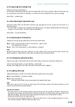
[Target Unit Deletion button]

Pressing the Target Unit Deletion button after selecting a target unit in the Target Unit List will delete the
selected unit from the list. Multiple target units can also be selected for deletion. 

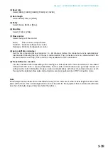
(4) Audio Stream Target Port

Enter the port number of the target unit to be used by the audio stream.

(5) Save button

Updates the NX-100/100S setting file.
When adding a pattern, the unit's name appears in the Programmed Pattern List.

Note

The broadcast control port number and audio stream target port are displayed in the "Network Setting"
screen for the target unit. (Refer to 

p. 4-4, NETWORK SETTING

.)

Caution

Never restart the unit or turn off the power during updates, or while the STATUS indicator on the front
panel of the NX-100/100S is flashing.

Summary of Contents for NX-100

Page 1: ...ON SETUP MANUAL NETWORK AUDIO ADAPTERS NX 100 NX 100S Thank you for purchasing TOA s Network Audio Adapter Please carefully follow the instructions in this manual to ensure long trouble free use of your equipment ...

Page 2: ... LOCATIONS 2 7 5 SOFTWARE INSTALLATION 5 1 System Conditions 2 8 5 2 Activating the Setup Launcher 2 8 5 3 Installing Java Runtime Environment 2 9 5 4 Installing the NX 100 Software 5 4 1 Installation procedures 2 11 5 4 2 Update information 2 14 5 4 3 Installation folder configuration 2 15 5 5 Uninstalling Each Software 2 15 1 GENERAL DESCRIPTION 1 1 What is the NX 100 Setup Program 3 2 1 2 About...

Page 3: ...le 3 14 6 2 2 Edit 3 14 6 2 3 Setting 3 14 6 2 4 Help 3 14 6 2 5 Buttons 3 15 6 3 Network Setting 3 16 6 4 Broadcast Spec Setting 3 18 6 5 Broadcast Pattern Setting 6 5 1 Setting new broadcast patterns 3 20 6 5 2 Editing broadcast patterns 3 22 6 6 Contact Setting 6 6 1 Contact input setting 3 23 6 6 2 Contact output setting 3 25 6 7 Serial Bridge Setting 3 27 6 8 System Settings 3 29 6 9 Saving t...

Page 4: ...g 4 21 8 2 Saving Operation Logs 4 23 8 3 Stream Logs 4 24 8 4 Operation Status 4 26 9 SYSTEM MANAGEMENT 4 27 1 NX 100 OPERATION PROGRAM SUMMARY 5 2 2 STARTUP AND INITIAL SCREEN 5 2 3 OPERATION SCREEN DESCRIPTION 5 3 4 MENU 4 1 File 5 4 4 2 Settings 5 4 4 3 Help 5 4 5 SETTING PROCEDURES USING THE OPERATION PROGRAM 5 5 6 UNIT SETTING ADDITION 5 6 7 EDITTING THE BUTTON LAYOUT 5 8 8 SETTING THE SELEC...

Page 5: ... Broadcast and Unit Scan 6 3 1 4 Multicast and Simultaneous Multiple Broadcasts 6 4 1 5 Packet Loss Recovery 6 4 1 6 Contact OFF Delay Time 6 4 1 7 Sampling Frequency Correction 6 4 2 INDICATOR STATUS AND TROUBLESHOOTING 6 5 3 IF A FAILURE IS DETECTED 6 7 4 SPECIFICATIONS 4 1 NX 100 6 9 4 2 NX 100S 6 10 Chapter 6 APPENDIX ...

Page 6: ...Chapter 1 BEFORE INSTALLATIONS AND SETTINGS ...

Page 7: ...ible Transmission of serial data control information also possible Simultaneous bi directional transmission of audio signals possible Simultaneous transmission of audio signals to multiple locations up to 4 locations for unicast 1 streaming 64 locations for multicast 2 streaming possible Enables loss free audio signal transmission even over congested networks such as the Internet The entire system...

Page 8: ... Input volume control 20 4 Input Peak Indicator Red Remains lit while the input audio signal is being distorted Set the Input volume control 20 and the Input level selection switch 21 to a proper position according to the input signal level 5 Status Indicator Yellow Remains lit during broadcasts Flashes while the unit is writing data into the internal storage medium flash memory 6 Error Indicator ...

Page 9: ... OUTPUT An open collector output Withstand voltage 30 V DC Control current 50 mA maximum 17 Control Input Terminal CONTACT INPUT A no voltage make contact input Short circuit current 10 mA Open voltage 12 V 18 Audio Output Terminal AUDIO OUTPUT A 0 dB 600 Ω balanced output Line level audio signal output H Hot C Cold E Ground shield 19 Audio Input Terminal AUDIO INPUT A 58 to 0 dB 2 kΩ balanced inp...

Page 10: ... 4 does not light 21 Input Level Selection Switch LINE MIC Set this switch to the MIC right side position when using a microphone and to the LINE left side for other inputs Factory preset to the LINE position 22 Phantom Power ON OFF switch PHANTOM The supply voltage is 24 V DC To supply the phantom power to the microphone connected to the Audio input terminal 19 set the Input level selection switc...

Page 11: ... is required to make broadcasts from the PC The Operation Program performs settings using the setting data prepared in 3 System Setting above Note Refer to Chapter 5 Operation Settings NX 100 Operation Program for the setting procedure 3 System Setting There are two setting methods 1 Setting Using NX 100 Setup Program This method permits integrated settings and management of the entire system by a...

Page 12: ...Chapter 2 UNIT AND SOFTWARE INSTALLATIONS ...

Page 13: ...ble adapter consult your TOA dealer Cord clamp AC adapter SIGNAL GND 10 100M DC 24V 200mA INPUT Ferrite clamp SFC 8 supplied with the NX 100S only This figure represents the NX 100S Note When noise interference affects voice output connecting the unit s Earth terminal FG terminal for the NX 100 SIGNAL GND terminal for the NX 100S to the ground terminal of the connected amplifier or mixer may impro...

Page 14: ...ions To microphone or other sound sources To mixer amplifier etc H C E H C E The NX 100 100S automatically distinguishes between 10BASE T and 100BASE TX networks and establishes a connection For this connection use a straight UTP Category 5 LAN Ethernet cable fitted with an RJ 45 connector Tip It is recommended that the unit be connected to network equipment capable of performing full duplex commu...

Page 15: ...rol a power distributor or PA amplifier mounted in the same rack as the unit using the unit s control output terminals provide an external relay and power supply as shown below to perform control with the relay contacts No voltage make contact input Short circuit current 10 mA Open voltage 12 V Pulse width Over 50 ms Control Input Specifications To other unit s control output Connections to the Co...

Page 16: ...ratures Wiring procedure Step 1 Wiring the supplied removable terminal plug 1 1 Loosen the terminal screws to insert the wire 1 2 Tighten the terminal screws Ensure that the wire does not break free when pulled If the wire does pull free repeat the connection procedure from the start Step 2 Insert the wired terminal plug into the corresponding terminal block in the unit s rear panel Step 3 Tighten...

Page 17: ... COL SIGNAL IN PU T PE AK ST AT US ER ROR RUN RES ET 00 05 F9 FF 80 81 NET WORK AU DIO AD AP TE R NX 10 0S LN K AC T FD COL SIGNAL INPU T PE AK ST AT US ER ROR RUN RES ET NX 100 100S NX 100 100S M3 x 10 machine screw 2 supplied with NX 100 100S M3 x 10 machine screw 2 supplied with NX 100 100S Rack mounting bracket 1 Fiber washer for M5 1 Coupler 1 5 x 12 rack mounting screw 1 M3 x 6 oval head scr...

Page 18: ...association with its corresponding installation location Be sure to record the relationship during installation to facilitate later network settings A 12 digit hexadecimal address number peculiar to and assigned to the network connected unit 00 05 F9 FF 80 81 NETWORK AUDIO ADAPTER NX 100 LNK ACT FD COL STATUS ERROR RUN RESET MAC address This figure represents the NX 100 ...

Page 19: ...automatically started when the supplied CD ROM is inserted into the PC s drive Note The Setup Launcher will not be automatically activated when the CD ROM is inserted if the PC s CD drive is not compatible with an auto run function In such cases execute the Setup Launcher file below using Explorer or My Computer or select Start Run on the taskbar to enter the command below Drive in which a CD is i...

Page 20: ... Quit other activated applications before installation Step 2 Click J2SE Runtime Environment 5 0 Update 3 of the Setup Launcher The installer will be activated Step 3 Select I accept the terms in the license agreement and Typical then click the Next button as instructed by the screen Installation will begin and the progress status displayed The Installation Completed indication will be displayed u...

Page 21: ...2 10 Chapter 2 UNIT AND SOFTWARE INSTALLATIONS Tip Check the correct Runtime installation or version number from Control Panel Installation completion icon ...

Page 22: ...ation Setting Enables integrated setting of the NX 100 and NX 100S from the PC NX 100 Operation Program Enables integrated setting of the NX 100 and NX 100S from the PC for broadcast activation Install this software program to operate the unit from the PC 5 4 1 Installation procedures Step 1 Click NX 100 Software in the Setup Launcher The installer will be activated ...

Page 23: ...different folder from the one displayed press the Change button to select the desired folder Press the Next button if the currently displayed folder is correct The Setup Type screen will be displayed Step 2 Click the Next button The screen Destination Folder will be displayed ...

Page 24: ... selected Installation will begin If NX 100 Software Custom Setup is selected The screen for selecting the software program to install in Custom Setup mode is displayed 4 1 Click the icon to select software program The popup menu for selecting the installation method will be displayed 4 2 Select This feature will be installed on local hard drive for the software program s to be installed and This ...

Page 25: ...est versions of the following software and manuals are open to the public on the Toa s download site http www toa products com international NX 100 firmware NX 100 software Setup program and Operation program and Instruction manuals Installation setup manual and Operations manual Please download them from the above web site To confirm the NX 100 software version use the Help menu of the software T...

Page 26: ...up Program Installation Setting packet_audio jar data data folder System nxc setup program system file panel nxc operation program system file IP address log unit operation log file Data in the data folder are commonly used by both the Setup Program and the Operation Program The Setup Program and the Operation Program always operate based on the unit setting files in the data folder Manually openi...

Page 27: ...Chapter 3 SYSTEM SETTINGS NX 100 SETUP PROGRAM ...

Page 28: ...he network management personnel before performing network settings for the PC and connected units Incorrect settings may adversely influence other units connected to the same network 1 3 Backing Up Setting Files Setting contents once saved are saved in the data folder located inside the Setup program s installation folder Default path C Program Files TOA NX 100 as a unit setting file If uploaded t...

Page 29: ...tool first scan the NX 100 and NX 100S units connected to the LAN for the system initial setting System Setting Tool Performs settings of unit broadcast contact serial bridge etc It is possible to create the system setting file beforehand by entering a unit setting before installation Setting Item Unit Scanning Tool Unit scanning See p 3 10 IP address See p 3 11 Subnet mask See p 3 12 Default gate...

Page 30: ...rform Broadcast Spec settings based on the network configuration Before using this function confirm the following information with network management personnel Usable bandwidth Whether or not multicast streaming can be used Broadcast Pattern Set the units to be connected in each broadcast pattern when activated by contact or the Operation program This setting not needed for units that will not be ...

Page 31: ... 100 only 2 Saving Data Files Save the data folder located in the Setup program s installation folder to the PC s hard disk drive or a connected external storage device Also be sure to save backup copies 3 Unit Scanning Network Setting After installing the system s Setup program on site copy the contents of the data folder saved in Step 2 above to the data folder After setting the network using th...

Page 32: ... password are case sensitive The default system name is factory preset to NX 100 and the password to guest To change them refer to p 3 31 When the system name and password are entered correctly the initial Installation Setting Program screen is displayed Tip At startup the Setup program automatically loads data related to unit setting from the data folder Step 3 When scanning the unit click on Uni...

Page 33: ...nfiguration Tip When the settings are saved a unit setting file is automatically created for each individual IP address and saved in the data folder If a unit setting file of the same name already exists in the data folder it is overwritten Step 5 Click on Password Change to change the password Step 6 Click on End to exit the program ...

Page 34: ...reen displayed after the units have been scanned 1 Scanned unit list A list showing the units scanned 2 MAC address Displays the MAC addresses of the units scanned Cannot be changed 3 Unit type Displays either type of unit NX 100 or NX 100S 4 IP address Displays the IP addresses of the units scanned 5 Subnet mask Displays the subnet mask to be set for the units scanned 6 Default gateway Displays t...

Page 35: ...em Setting Tool settings copy and save the data folder under a different name If the data folder is copied the unit setting file can be written into the NX 100 and the NX 100S after copying the renamed folder to the data folder even when Save in setting file format is selected 2 After Unit Scanning Tool settings have been performed use the System Setting Tool after uploading the settings but witho...

Page 36: ...units to the network and turn on each power The LNK ACT Indicator will light Step 2 Either press the Unit Scan Button or select Scan Unit scan The MAC address IP address subnet mask default gateway and unit name of the NX 100 and NX 100S connected to the LAN will be displayed Default values are factory preset as follows IP address 192 168 1 1 Subnet mask 255 255 255 0 Default gateway 0 0 0 0 Name ...

Page 37: ...dress Assignment Set the IP address for the unit scanned Besides the Changing the Unit Setting Values method described in the previous item there is another method for automatically assigning addresses by limiting the IP address setting range Step 1 Select the unit to which the address is assigned by ticking its selection checkbox To assign the same address to all units select Scan Select all Step...

Page 38: ... Tick the selection checkbox to select the unit To select all units select Scan Select all Step 2 Set the subnet mask 2 1 Select Scan Subnet mask setting 2 2 A dialog will be displayed Enter the setting value and click on the OK button Step 3 Set the default gateway 2 1 Select Scan Default gateway setting 2 2 A dialog will be displayed Enter the setting value and click on the OK button ...

Page 39: ... Clicking on System Setting on the Installation Setting Program s initial screen displays the following window If the unit to be set is selected its currently set contents are displayed in the right side setting form 1 Name Displays the unit names programmed into the system 2 IP address Displays the unit IP addresses programmed into the system 3 Web server port Displays the port number of the web ...

Page 40: ...reen NX 100S Adds the selected NX 100S to the list edit screen Delete Deletes the selected NX 100 or NX 100S from the list edit screen Clear Deletes all NX 100 and NX 100S units from the list edit screen 6 2 3 Setting Upload Ctrl U Writes the settings currently being edited into the NX 100 and NX 100S Download Ctrl D Downloads the settings from the NX 100 and NX 100S and displays them on the edit ...

Page 41: ...twork list edit screen 3 NX 100S Add button Adds NX 100S units to the network list edit screen 4 Delete button Deletes NX 100 and NX 100S units from the network list edit screen 5 Upload button Writes the currently edited settings into the NX 100 and NX 100S 6 Download button Downloads NX 100 and NX 100S settings and displays them on the edit screen Not saved 1 2 3 4 5 6 ...

Page 42: ...ress Enter the unit s IP address After the IP address is set with the Unit Scanning Tool the assigned IP address is indicated when the unit setting file is loaded into the PC 2 TCP port number assignment Designate the web server port number and the base number of the other TCP port The port number can be set within the range of 1 65535 Web server Enter the web server port number Its default is 80 ...

Page 43: ...TCP TCP TCP Default 80 5000 5001 5002 5003 3 UDP port number assignment Designate the base port number to be used by UDP Start port No Enter the base UDP port number to be used by the unit The default is 5000 Enter an even number from within the range of 1 65526 The UDP ports are assigned as follows Port Streaming Error correction Resend Serial bridge Fs correction Port No Start port No 0 Start po...

Page 44: ... 3 Set each item while referring to the bandwidth and delay time indicated in the Information area located at the bottom of the screen Caution Broadcasts are interrupted when the set bandwidth is displayed in red in the Information area The bandwidth is indicated in red whenever this setting exceeds the per stream usable bandwidth 1 Sampling frequency kHz Select a sampling frequency for both trans...

Page 45: ... packet is lost Standard Error Correction and Resend Refer to p 6 4 for details regarding each recovery method If Error Correction is selected A scale for setting the correction level appears Higher settings increase correction capability however delay times are also made longer If Resend is selected A scale for setting delay times appears Longer delay times increase correction capability 5 Enable...

Page 46: ...r 3 SYSTEM SETTINGS NX 100 SETUP PROGRAM 6 5 Broadcast Pattern Setting 6 5 1 Setting new broadcast patterns Step 1 Click on the Broadcast Pattern tab of the System Setting Tool The setting screen will be displayed ...

Page 47: ...nected NX 100 and NX 100S units Local Makes broadcasts from the Audio Input of the NX 100 or NX 100S unit to its Audio Output Selecting Transmission or Reception permits selection of the connected unit Caution Local broadcasts cannot be made when the transmission sampling frequency is set to 32 kHz in the Broadcast Spec setting Step 5 Select the connected unit from the displayed list when Transmis...

Page 48: ...ng Tool The setting screen will be displayed Step 2 Click on the broadcast pattern to be edited The setting contents are displayed in the edit area allowing editing Tip To delete a previously programmed broadcast pattern click on the broadcast pattern to be deleted then press the Delete button Step 3 Re enter or reselect the section to be changed ...

Page 49: ...6 6 1 Contact input setting Step 1 Click on the Contact tab of the System Setting Tool Step 2 Click on the selection button for the contact input channel number The setting contents will be displayed Step 3 Tick the Enable contact checkbox The setting contents can be edited ...

Page 50: ...entary ON ON ON ON ON ON ON ON ON ON Activation Stop Activation Stop Step 5 Set Polarity to Make or Break Make ON when the contact is closed Break ON when the contact is opened Step 6 A list of the programmed broadcast patterns is displayed in the Broadcast pattern screen Tick the checkbox to select the pattern Cautions Broadcasts cannot be made if the set frequency band exceeds the usable bandwid...

Page 51: ...eckbox for Enable contact The setting contents can be edited Step 4 Select Mode from Standard STATUS Output and ERROR Output Standard Provides output by way of control from a PC or contact inputs of other units or original unit STATUS Output Provides contact output synchronizing with the unit s STATUS indicator operation ERROR Output Provides contact output synchronizing with the unit s ERROR indi...

Page 52: ...Break Momentary ON ON ON ON ON ON ON ON ON ON Activation Stop Activation Stop Caution The unit s correct operation cannot be ensured if both activation and stop signals are received during the 1 second output interval Step 6 Select Polarity from Make or Break Make ON when the contact is closed Break ON when the contact is opened Step 7 Set OFF delay time from 0 60 seconds Adjust the displayed scal...

Page 53: ...ommunication method TCP server The unit selected on the setting screen functions as a TCP server and carries out communications TCP client The unit selected on the setting screen functions as a TCP client and carries out communications Clicking the radio button permits selection of the connected unit UDP Carries out UDP communications Clicking the radio button permits selection of the connected un...

Page 54: ...ted if the timeout duration is set to 0 This function is only available for TCP connections 9 Transmit receive raw data Tick the checkbox when transmitting and receiving raw data Data with control information to be utilized between NX 100 units is usually transmitted but raw data communications are generally carried out without such control information However when communications with other connec...

Page 55: ...dio input unit connected to the unit 3 Audio output Enter the name of the audio output unit connected to the unit 4 Firmware version Indicates the unit s firmware version number 6 9 Saving the Unit Setting Files Save the unit setting file to the specified location The data folder is located in the installation folder Default path C Program Files TOA NX 100 of the setup program The save location ca...

Page 56: ...e upload The Status indicators on the NX 100 s and NX 100S front panels flash during the upload 6 13 Downloading Unit Setting Files Read the currently connected NX 100 s and NX 100S setting contents into the System Setting Tool Click on the Download button or select Setting Download Programmed setting data of the units connected to the system will be displayed 6 14 Updating Firmware Update the fir...

Page 57: ...screen In the Management Setting Program select Help Version data and a dialog will then be displayed Click on the Change password button The Password Change screen will be displayed Step 2 Enter a new system name and password Use up to 15 alphanumeric characters to enter the system name and password They can be set to blank Enter the password a second time for verification ...

Page 58: ...Chapter 4 SYSTEM SETTINGS SETTING USING BROWSER ...

Page 59: ...rk as the PC Complete network settings before using the NX 100 Installation Setting program If performing setup by the browser disconnect the unit from the network and connect it directly to the PC s LAN port using a cross cable Should the power be switched off during setting changes the unit may be damaged Changed settings are enabled after the NX 100 100S is restarted Be sure to restart the unit...

Page 60: ...re correctly entered This figure represents the NX 100 Step 3 Set each item Referring to the corresponding pages perform each setting Note that serial bridge setting can be performed for the NX 100 only Caution When displaying each browser setting screen the screen is not correctly displayed if the Back or Forward button of the browser is used Use the menu on the left hand side of the window Menu ...

Page 61: ...This figure represents the NX 100 1 IP Address Enter the NX 100 100S unit s IP address Factory preset to 192 168 1 1 2 Subnet Mask Set the mask address Factory preset to 255 255 255 0 3 Default Gateway Enter the gateway address if the unit is being used outside its assigned subnet Factory preset to 0 0 0 0 ...

Page 62: ...y the NX 100 100S Range 1 65532 Factory preset 5000 UDP Port No Assignment Designate the first port number to be used by the UDP Start port no Enter the first UDP number to be used by the unit Range EVEN numbers 1 65526 Factory preset 5000 Caution Since UDP port No 15000 is used by the unit numbers between 14990 and 15000 cannot be used 5 Save button Updates the NX 100 100S setting file Caution Ne...

Page 63: ...sts based on this setting This figure represents the NX 100 1 Navigator Select the usable bandwidth and type of line and press the Set button A recommended values will then be set If no problems are foreseen perform the setting as is without changing these values Note Be sure to consult with network management personnel regarding bandwidth type of line and multicast streaming ...

Page 64: ...adcasts from the original unit to other units Broadcast signals can be sent to a connected unit if the transmission bandwidth is within the set bandwidth Reception only broadcasts from other units to the original unit Broadcast signals can be received from a connected unit if the reception bandwidth is within the set bandwidth Local broadcast transmissions from the original unit s audio input to i...

Page 65: ... this setting while taking care that the same number is not duplicated among the units connected to the same network Note Be sure to consult with network management personnel before performing this setting 5 Sampling Frequency Correction Refer to p 6 4 for sampling frequency correction Transfer Setting between Networks Perform the setting to transfer sampling frequency correction data between diff...

Page 66: ...ts the broadcast when a contact or program operation input is received Local broadcasts which do not use the network or single stream broadcasts can also be set as broadcast patterns Target receiving unit 1 Target unicast transmission unit 1 Target multicast transmission units 64 Create a new broadcast pattern by clicking on the Pattern Addition button or select and edit a pattern which has alread...

Page 67: ...to the programmed pattern list and displayed in the pattern selection area 4 Pattern Deletion button Deletes the selected broadcast pattern and updates the NX 100 100S setting file Caution Never restart the unit or turn off the power during updates or while the STATUS indicator on the front panel of the NX 100 100S is flashing 5 2 Pattern Edit Area The pattern addition display differs from the pat...

Page 68: ...nit list Example of addition to the Target Unit list Caution Units are not added by merely entering them in the Target Unit Addition frame Be sure to confirm that the unit is added to the list after the Target Unit Addition button is pressed and then press the Save button The Target Unit Addition button is automatically disabled when target units can no longer be added Target Unit Deletion button ...

Page 69: ...the pattern before being changed are displayed The setting contents of the pattern are also displayed in the pattern edit area for editing This figure represents the NX 100 Press the Save button to program the edited pattern Pressing the Save button will update the NX 100 100S setting file Caution Never restart the unit or turn off the power during updates or while the STATUS indicator on the fron...

Page 70: ...t s contact outputs Here contact input and output settings are performed This figure represents the NX 100 1 Contact Selection Select the contact to be set Selecting the input or output channel number of the contact displays its contact s setting contents 2 Enable Disable Selection Select Enable or Disable for the contact Select Enable when using the contact function All setting items are then rea...

Page 71: ... activated while the input is ON The start mode stops when the input is OFF Latch When the input is turned on the designated broadcast pattern or other unit s contact is activated and the start mode continues even if the input is turned OFF The start mode stops when the input is turned ON again 50 ms or more 50 ms or more Broadcast and contact data Contact input Contact input Latch Broadcast and c...

Page 72: ...roadcast If NO is displayed for a pattern review the Broadcast Spec settings Bandwidth Indicates the total bandwidth used by the set pattern Caution Broadcasts cannot be made if the setting exceeds the available bandwidth 4 Contact Bridge The Contact Bridge refers to the function that enables the contact outputs of other connected unit or original unit when the original unit s contact input is act...

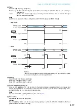
Page 73: ...Enable and set the contact output contents This figure represents the NX 100 1 Mode Select Mode from Standard STATUS Output and ERROR Output Standard Provides output by way of control from a PC or contact inputs of other units or original unit STATUS Output Provides contact output synchronizing with the unit s STATUS indicator operation ERROR Output Provides contact output synchronizing with the u...

Page 74: ... Activation Stop Caution The unit s correct operation cannot be ensured if both activation and stop signals are received during the 1 second output interval 3 Polarity Select Polarity from Make and Break Make ON when the contact is closed Break ON when the contact is opened 4 Contact OFF Delay Time sec Enter an OFF delay time of 0 60 seconds for the duration between receiving a termination request...

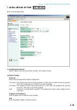
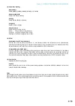
Page 75: ... unit carries out communications as a TCP server The NX 100 unit connected to this server must be set as a TCP client in its protocol settings TCP Client The original unit carries out communications as a TCP client The target NX 100 unit must be set as a TCP server in its protocol settings UDP Carries out communications using UDP The target NX 100 unit s protocol settings must be set to UDP Target...

Page 76: ...nnections Transmit Receive RAW data Tick the checkbox when transmitting and receiving raw data Data with control information to be utilized between NX 100 units is usually transmitted but raw data communications are generally carried out without such control information However when communications with other connected units are cut off this cannot be detected Raw data communications are only possi...

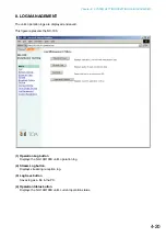
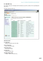
Page 77: ...splayed and saved This figure represents the NX 100 1 Operation Log button Displays the NX 100 100S unit s operation log 2 Stream Log button Displays streaming reception log 3 Log Save button Saves log as a file in the PC 4 Operation Status button Displays the NX 100 100S unit s current operation status ...

Page 78: ... pressed on the Log Management Menu screen This figure represents the NX 100 Operation button 1 Latest button Updates the operation log to current data 2 Prev Page button Moves to the previous page 3 Next Page button Moves to the next page 4 Clear button Deletes all operation logs 5 Display Change button Displays or hides the web access log ...

Page 79: ...TCH Monitoring of the contact input and the contact control SERIAL Serial bridge operating status SYSTEM System information WEB Web server access log STREAM Status of audio stream 3 Requesting Source Indicates the IP addresses of communication parties or requesting sources of the events such as designating contact channels 4 Contents Indicates the contents of events Levels are Normal green Caution...

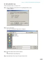
Page 80: ... the Operation Log Save button on the Log Management Menu screen A dialog is displayed Step 2 Press the Save Button The screen for selecting the storage location is displayed Step 3 Select the storage location and enter a filename Tip The default filename is IP address log Step 4 Select All files for Save as type then press the Save button ...

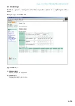
Page 81: ...am Logs The Stream Log screen is displayed when the Stream Log button is pressed on the Log Management Menu screen This figure represents the NX 100 Operation Button 1 Refresh button Updates to the most recent data 2 Clear button Deletes all stream reception logs ...

Page 82: ...mber of packets whose packet length and header data are not matched Restoration The number of packets recovered by error correction or resending out of those that were lost due to network failures Loss The number of packets not recovered out of those lost due to network failures Silent tone insertion The number of packets that caused no sound from the audio output 2 Past Reception Log The network ...

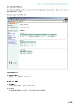
Page 83: ...peration Status button is pressed on the Log Management Menu screen This figure represents the NX 100 Operation Button 1 Refresh button Updates status to the most recent data Item in the Table 1 Broadcast Indicates the condition of the current broadcast 2 Contact Indicates the conditions ON OFF of the contact input and output ...

Page 84: ...Utility area is not displayed when in Management Setting mode Unit Data 1 Unit Name Enter the NX 100 100S unit s name 2 Audio Input Unit Name Enter a name when connecting the audio input unit 3 Audio Output Unit Name Enter a name when connecting the audio output unit This figure represents the NX 100 ...

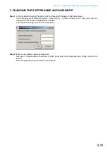
Page 85: ...name is displayed Use up to 15 alphanumeric characters to enter the system name It can be set to blank Step 2 Enter a new password in the New Password frame Tip Use up to 15 alphanumeric characters to enter the password It can be set to blank Step 3 To confirm enter the password entered in Step 2 in the New Password verification frame Enter the same password again for verification Step 4 Press the...

Page 86: ...ing files Step 1 Press the Browse button The Choose file dialog opens Step 2 Select the backup file cfg extension then press the Upload button Update of the setting file begins Caution Never restart the unit or turn off the power during updates or while the STATUS indicator on the front panel of the NX 100 100S is flashing ...

Page 87: ...ng file Step 1 Press the Download button A dialog is displayed Step 2 Press the Save button A dialog is displayed Step 3 Select the save destination and enter a filename Tip The default filename IP address cfg is first displayed Step 4 Select All files for Save as type then press the Save button ...

Page 88: ...flashing Tips The latest versions of the following software and manuals are open to the public on the Toa s download site http www toa products com international NX 100 firmware NX 100 software Setup program and Operation program and Instruction manuals Installation setup manual and Operations manual Please download them from the above web site The version of each instruction manual is in the lowe...

Page 89: ...Chapter 5 OPERATION SETTINGS NX 100 OPERATION PROGRAM ...

Page 90: ...tern can be set per button Note For more information concerning broadcast pattern settings refer to Chapters 3 and 4 2 The NX 100 s and NX 100S contact output is controlled via the network Up to 64 units x 8 channels can be controlled per button 2 STARTUP AND INITIAL SCREEN Either double click on the Operation program icon created on the desktop at the time of program installation or double click ...

Page 91: ...pattern or up to 64 units X 8 contact output channels can be set per Selection button 2 Group Button Used to simultaneously select two or more Selection buttons The number of buttons programmed is 10 by default 3 Start Button Starts up the activation contents broadcast pattern and contact output selected with the Selection or Group buttons This button can be hidden from display depending on the se...

Page 92: ...gs Button setting Set the Selection button and the Group button Unit settings If there is a unit that has not yet been programmed into the system using the NX 100 setup program select this menu item to add it as the operable unit 4 3 Help Help Displays help contents Version data Indicates the version number of the software program in use ...

Page 93: ...tputs to be activated Use the broadcast patterns which were programmed into the operable units those units set with the NX 100 Setup program and added in Step 1 above Only one pattern can be programmed into each Selection button When simultaneously activating two or more broadcast patterns with the Group button all of the broadcast patterns to be activated must first be programmed into the Selecti...

Page 94: ...llowing procedure Step 1 Turn on the power to the NX 100 and NX 100S units for which the unit setting is to be added to make connections possible Step 2 Start up the Operation program and select Setting Unit settings The User Authentication screen is then displayed Step 3 Enter the system name and the password the same password used in the setup program then press the OK button Notes Both the syst...

Page 95: ...he software program installation folder Step 7 Press the OK button after all necessary NX 100 and NX 100S units have been added The NX 100 and NX 100S units with the entered IP addresses are connected and their setting data downloaded After the downloading of all units is completed the Unit Settings screen is closed The downloaded setting contents are saved to the data folder in the software progr...

Page 96: ...uthentication screen is displayed Step 2 Enter the system name and the password the same system name and password entered in the setup program then press the OK button Notes Both the system name and the password are case sensitive The default system name is preset to NX 100 and the password to guest when the unit is shipped from the factory To change refer to p 3 31 or p 4 28 The Button Setting sc...

Page 97: ... buttons Set the number of buttons on the operation screen There is no limit to the number of buttons that can be set 2 Single selection button horizontal vertical Set the number of Single Selection buttons The number is preset to 5 horizontal by 10 vertical buttons total 50 buttons 3 Group button horizontal vertical Set the number of Group buttons The number is preset to 1 horizontal by 10 vertic...

Page 98: ...e operation screen 3 Indication Name The name of the Selection button to be displayed on the operation screen Selection button layout Example when 5 horizontal by 10 vertical buttons are set 8 SETTING THE SELECTION BUTTON CONTENTS Program the broadcast pattern and the contact output activation setting into the Selection button Step 1 Click on the Single selection button tab on the Button Setting s...

Page 99: ...ze at startup is 16 Because the number of displayed characters increases as the display screen increases in size set the number of characters to correspond to the screen size to be used Step 5 Check the broadcast pattern to be activated in the Broadcast pattern list Tips The Broadcast pattern list displays all patterns that have been programmed into all NX 100 and NX 100S units in the system inclu...

Page 100: ...s of all NX 100 and NX 100S contact outputs press the leftmost Clear button in the Edit area Step 8 Press the OK button after completing all editing tasks The setting contents are saved to the data folder located in the installation folder default path C Program Files TOA NX 100 of the software program and the Button Setting screen is closed ...

Page 101: ...ion Contents List 1 Enable Displays or hides the Group buttons 2 No Group button numbers These numbers cannot be changed The buttons are arranged in the order of the button number see figure at right on the operation screen 3 Indication Name The name of the Group button to be displayed on the operation screen Group button layout Example when 1 horizontal by 10 vertical buttons are set Step 2 Click...

Page 102: ...tton list displays the numbers and names of the Selection buttons Only the Selection buttons programmed on the Single selection button setting screen can be checked If an invalid combination is set for broadcast an error message will be displayed when the Start button is pressed on the operation screen To clear the setting contents of the selected Group button press the Clear button Step 6 To save...

Page 103: ...ayed in the message display area the NX 100 100S may be malfunctioning or have failed Note In the above messages OO indicates a unit s name and IP address and XX indicates the channel number Message OO connection failure Connection failure to all designated units OO connection failure Incomplete broadcast No broadcast Connection failure to all units Interrupted broadcast to OO Interrupted broadcas...

Page 104: ...Chapter 6 APPENDIX ...

Page 105: ...units through the Internet fixed global IP addresses must be acquired and assigned to them or the router if it is used When a connection is made from Unit B to Unit A in the figure the local address can be used However when a connection is made from Unit C to Unit A the global IP address must be used The fixed global IP address must be assigned to the units connected via the Internet When selectin...

Page 106: ...n unit for the broadcast pattern contact or serial bridge in the NX 100 and NX 100S unit settings The serial bridge function is valid only for the NX 100 1 3 IP Broadcast and Unit Scan The IP broadcast communication method is used to scan the units connected to the network Units can only be scanned within the effective range of the IP broadcast The address to be used is 255 255 255 255 NET1 NET2 R...

Page 107: ... networks as the Internet which may generate many packet losses This method however is not well suited to applications that emphasize real time operability because of longer delay times Standard Note Numbers represent level of advantage in the order of 1 2 3 Error correction Resend Packet loss recovery ability Real time operability Band occupation 3 1 Small 2 2 Moderate 1 3 Large 1 6 Contact OFF D...

Page 108: ...Error Indicator Red Firmware exception handling Communications error on for 1 s then off 7 Run Indicator Green CPU normal operation CPU malfunction NX 100S only NX 100S only Normal indicator status Description Continues for 30 seconds after the unit is turned on If this status remains unchanged over 30 seconds this shows unit failure Contact your TOA dealer Normal condition when broadcast is not p...

Page 109: ...sion occurrence The NX 100 100S and the connected network equipment are in half duplex communications and collision occurs This may cause intermittent sound when audio signals are transmitted It is preferable to use the NX 100 100S in full duplex communications Network disconnection LAN cable is disconnected or network equipment is turned off Ensure each connection to the network equipment Excessi...

Page 110: ...if the router is properly set If Java Runtime Environment is set to operate via a proxy server indications may not be properly displayed Cancel the use of proxy Perform this operation from the Control Panel Check PC using Setup Operation programs by way of browser for correct connection Also confirm that browser is correctly set Setting screen uses Java Script Confirm that browser is Java Script c...

Page 111: ...hen audio output is lost network may be congested Check log contents If congestion is found consult with network management personnel Refer to p 4 24 Stream Logs to confirm log contents When broadcasts are heard mixed in multicast streaming the same multicast address may have been set for some broadcasts in Broadcast Spec setting Avoid duplication of multicast address when performing settings for ...

Page 112: ...rmer isolated balanced 600 Ω removable terminal block Frequency Response 50 14 000 Hz when sampling frequency is 32 kHz Distortion Under 0 3 1 kHz when sampling frequency is 32 kHz Control Input 8 channels no voltage make contact input open voltage 12 V DC short circuit current 10 mA removable terminal block Control Output 8 channels open collector output polarized withstand voltage 30 V DC contro...

Page 113: ...ormer isolated balanced 600 Ω removable terminal block 3 pins Frequency Response 50 14 000 Hz when sampling frequency is 32 kHz Distortion Under 0 3 1 kHz when sampling frequency is 32 kHz Control Input 8 channels no voltage make contact input open voltage 12 V DC short circuit current 10 mA removable terminal block 9 pins Control Output 8 channels open collector output polarized withstand voltage...

Page 114: ...200708 URL http www toa jp ...

Reviews: