00-05-F9-FF-80-81
NETWORK AUDIO ADAPTER NX-100S
LNK/ACT
FD/COL
SIGNAL
INPUT
PEAK
STATUS
ERROR
RUN
RESET
1
2
3
4
5
6
7
8
9
1-3
Chapter 1: BEFORE INSTALLATIONS AND SETTINGS
3. NOMENCLATURE AND FUNCTIONS
[Front]
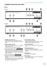
1. LNK/ACT Indicator (Green)
Lights when the unit is connected to a network.
Flashes while the unit is transmitting or receiving
data.
2. FD/COL Indicator (Yellow)
Remains lit while the network is in full-duplex
communications mode.
Flashes whenever data collision is detected.
3. Input Signal Indicator (Green)
Lights when the audio signal applied to the Audio
input terminal (19) is adjusted to a level enough
high for transmission to a network with the Input
volume control (20).
4. Input Peak Indicator (Red)
Remains lit while the input audio signal is being
distorted.
Set the Input volume control (20) and the Input
level selection switch (21) to a proper position
according to the input signal level.
5. Status Indicator (Yellow)
Remains lit during broadcasts.
Flashes while the unit is writing data into the
internal storage medium (flash memory).
6. Error Indicator (Red)
Lights if an error is detected during transmission,
etc.
7. Run Indicator (Green)
Remains lit during normal operation.
Flashes at 2-second intervals when a failure is
detected.
8. Reset Button
Restarts the unit when pressed.
9. MAC Address
The unit's MAC address consists of 12 hyphenated
alphanumeric characters.
NX-100S only
NX-100S only
00-05-F9-FF-80-81
NETWORK AUDIO ADAPTER NX-100
LNK/ACT
FD/COL
STATUS
ERROR
RUN
RESET
1
2
5
6
7
8
9
• NX-100S
• NX-100
Summary of Contents for NX-100
Page 6: ...Chapter 1 BEFORE INSTALLATIONS AND SETTINGS ...
Page 12: ...Chapter 2 UNIT AND SOFTWARE INSTALLATIONS ...
Page 27: ...Chapter 3 SYSTEM SETTINGS NX 100 SETUP PROGRAM ...
Page 58: ...Chapter 4 SYSTEM SETTINGS SETTING USING BROWSER ...
Page 89: ...Chapter 5 OPERATION SETTINGS NX 100 OPERATION PROGRAM ...
Page 104: ...Chapter 6 APPENDIX ...
Page 114: ...200708 URL http www toa jp ...


