6
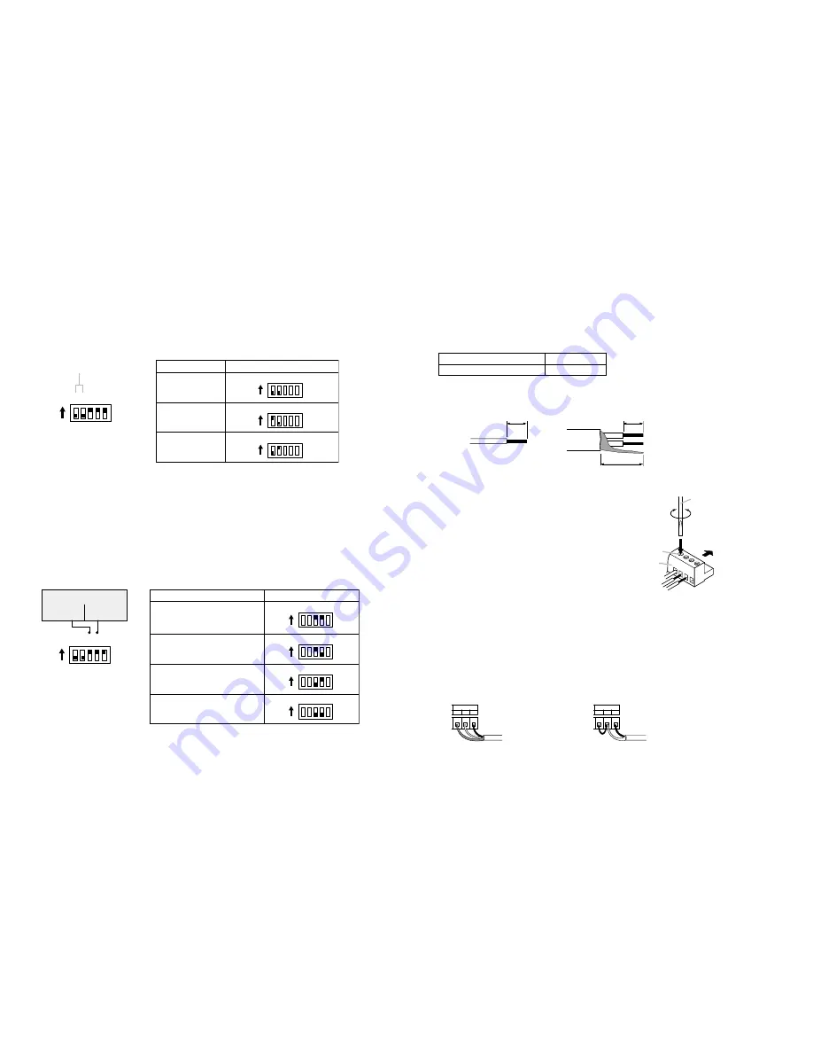
6. BROADCAST DELAY TIME SETTINGS
7. CHIME SETTINGS
The delay time between message activation and the actual start of playback can be set to 0, 2, or 4 seconds
with the unit's bottom-mounted Delay Time Setting DIP switches. (Factory-preset to "0" seconds.)
Should the beginning of playback contents be lost due to operational delays experienced by connected
external equipment, set the delay time to 2 or 4 seconds.
Note:
If the delay time is set to 2 or 4 seconds, the Busy Output terminal is closed during the delay as well.
Note:
Avoid simultaneously setting both the "1" and "2" switches to ON because the delay time cannot be
correctly set.
ON
5
4
1 2 3
Delay Time Setting DIP Switches
3: CHIME 1
4: CHIME 2
1: DELAY 2S
2: DELAY 4S
5: ALT/PTT
Set Delay Time
2 seconds
0 seconds
(Factory-preset)
4 seconds
ON
1 2
ON
1 2
ON
1 2
Delay Time Setting DIP Switches
TIP
When shipped, the chimes are set to sound an ascending 4-note tone before broadcast and a descending 4-
note tone after broadcast. The chime tones can be changed using the data transfer program found on the
supplied CD-ROM. For more information, please refer to the "EV20 Software Instruction Manual.pdf" file
located on the CD-ROM.
The built-in chime can be set to sound (or not) before and after recorded message broadcasts and direct
microphone announcements using the unit's bottom-mounted Chime Setting DIP switches.
Note:
The Chime switches are initially preset at the factory to sound chime tones before and after broadcasts
(both switches set to ON).
ON
5
4
1 2 3
ON
3 4
CHIME
ON
3 4
ON
3 4
ON
3 4
Chime Setting DIP Switches
3: CHIME 1
4: CHIME 2
1: DELAY 2S
2: DELAY 4S
5: ALT/PTT
Chime Setting DIP Switches
Pre-
announcement
Post-
announcement
Pre-announcement:
Post-announcement:
(Factory-preset)
Sounded
Sounded
Pre-announcement:
Post-announcement:
Sounded
Not sounded
Pre-announcement:
Post-announcement:
Not sounded
Sounded
Pre-announcement:
Post-announcement:
Not sounded
Not sounded
11
10.3. Connections to the Rear-Mounted Connectors
Notes
• Use the appropriate type of screwdriver for the connector wiring screws.
• When using stranded or shielded cable, do not solder the stripped and exposed ends.
When the cable is clamped, the solder becomes crushed, increasing contact resistance and possibly
resulting in an extreme rise in cable joint temperature.
Conductor cross-sectional area
0.5 – 1.5 mm
2
AWG
AWG24 – 16
Tighten
Loosen
Connector
(Accessory)
To unit's rear panel-
mounted socket
Terminal screw
Flat-blade screwdriver
1
2
Solid and stranded cables
Shielded cable
6 mm
6 mm
15 mm
10.3.1. Matching cable size
10.3.2. Stripped cable end
10.3.3. Cable connections
10.3.4. Line output terminal connections
Step 1.
Loosen the terminal screw to insert the cable into
the connector, then retighten the screw.
Note
Tug lightly on the cable to be sure that it does not
pull free. If the cable pulls free, loosen the terminal
screw again and reconnect from the beginning.
Step 2.
Insert the connector into the rear-mounted socket.
Notes
• Take care not to reverse Steps 1 and 2.
When tightening the terminal screw, force is applied to the connector pins on the internal circuit board,
possibly resulting in poor contact.
• Be sure all unused terminal screws are also tightened. Loose screws may produce rattling sounds in
response to monitor speaker vibration.
The Line output terminal is internally connected in parallel to the Line output jack. Do not use both terminals
simultaneously.
[Connection to a balanced amplifier] [Connection to an unbalanced amplifier]
LINE OUT
C
E
H
LINE OUT
C
E
H
To power amplifier
To power amplifier
Note
Short the E (ground) and C (cold) amplifier terminals
when using the Line output jack.


