background image

NOMENCLATURE AND SET-UP

S5.5-RX

3

3

NOMENCLATURE AND SET-UP

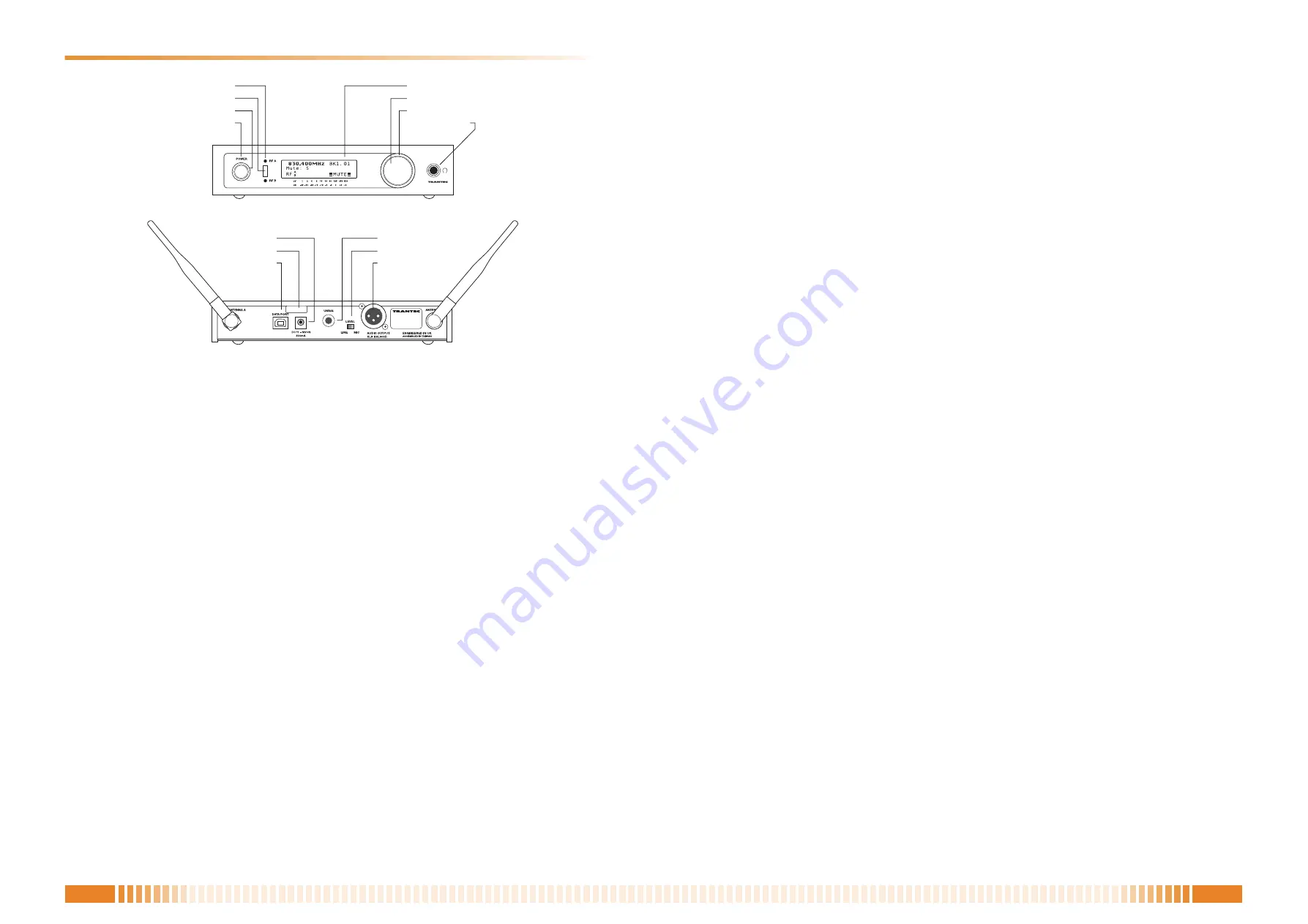
1. Attach the supplied antennae (2) to the rear panel TNC antenna connectors as shown in above illustra-

tion.

2. Connect the AC/DC adaptor into the DC inlet as marked on the rear panel using the attached cable strain

relief. Observe the front panel on-off switch surround is illuminated red.

3. Connect the rear panel AF output from either the 1/4" Jack or XLR to your mixing console or amplifier. 

Note: the XLR balanced output can be switched for either mic or line. The system can be also monitored

from the headphone socket using the "Jog-Wheel" to adjust Volume level.

4. Switch On-Off switch to "On" position and the receiver will default to initial setting as per illustration above.

(BK1.01)

The system is now ready for use.

Rear View

Front View


DC inlet 

1/4” jack output

  DC strain relief 

Mic/Line switch


USB port 

XLR output

 Diversity switch A/B indicators

Infra-red port

Power switch indicator

Power On/Off

LCD

Jog wheel

Mute indicator

Headphone output

Summary of Contents for S5.5-RX A1

Page 1: ...C1 D3 HS0910 NOTE ON REPAIR WORK SAFETY 2 SPECIFICATIONS 2 NOMENCLATURE AND SET UP 3 BLOCK DIAGRAM 4 SCHEMATIC DIAGRAMS MAIN PCB 5 LED PCB 9 MOUNTING DIAGRAMS AND PARTS LIST MAIN PCB 10 PARTS LIST MA...

Page 2: ...rength using parts other than those specified could result in a fire After replacing parts be sure to return the new parts and any other affected parts to their previous configuration Check that all s...

Page 3: ...Jack or XLR to your mixing console or amplifier Note the XLR balanced output can be switched for either mic or line The system can be also monitored from the headphone socket using the Jog Wheel to a...

Page 4: ...r Display usb interface IR Interface CHA AF Buf CHB AF Buf Comparator AF Switch Mute Sw Lo cut Phase invert Compander LPF De emphasis High boost Noise Mute Tone Mute Battery monitor Headphone Amp Phan...

Page 5: ...270K IC15B 4580 5 6 7 8 4 R162 22K C139 10n R164 2K2 R165 10K TR16 KTC4075 R166 10K C140 10n R167 4K7 C141 2u2_ELEC TR17 KTC4075 C142 2u2_ELEC C143 220p C144 220p R168 15K TR18 KTC4075 C145 1n TR19 KT...

Page 6: ...67 10n R189 4K7 R190 10K C168 10n C169 10n R191 100 C170 100p C171 100p C172 10n C173 10n C174 10n R192 2K2 C175 10n R193 470 C176 10n IC16 LA1225 IFI 1 REG 2 GND 3 SLVL 4 VCC 5 AFO 6 DET 7 IFO 8 STRQ...

Page 7: ...R91 47K C103 10u_ELEC R93 150K R94 100K_POT R95 DNP R96 47K IC10A 2904 3 2 1 C105 220n R97 100K C106 220n C107 220n IC11A 4066 1 2 13 R100 100K R101 100K C108 47u_ELEC C109 22n R102 100K IC11B 4066 11...

Page 8: ...C18 LM4811 VOUT1 1 VIN1 2 BYPASS 3 CLOCK 4 GND 5 UP DOWN 6 SHUTDOWN 7 VIN2 8 VOUT2 9 VCC 10 R220 10K C202 220n C204 10u_ELEC C205 10u_ELEC C210 47p TR36 KTC4075 R232 10K IC20A 4580 3 2 1 8 4 IC20B 458...

Page 9: ...W DISP_ENAB LE RD0 RD1 RD2 RD3 RD4 RD5 RD6 RD7 LCD_L ED_A LCD_L ED_A GND GND ENC 1 E27 SELECT 1 2 3 5 4 D1 RE D_LED D2 RED_LED D3 IR_ LED JP1 55 RIBBON 1 1 2 2 3 3 4 4 5 5 6 6 7 7 8 8 9 9 10 10 11 11...

Page 10: ...C29 D13 40 032 6X CAPACITOR U0603C102JNT C30 113 40 664 5X CAPACITOR 1608 50V 10NF TAP C31 113 40 632 0X CAPACITOR U0603C220JNT C32 DUMMY C33 DUMMY C34 113 40 637 5X CAPACITOR U0603C560JNT C35 113 40...

Page 11: ...TAP C175 113 40 664 5X CAPACITOR 1608 50V 10NF TAP C176 113 40 664 5X CAPACITOR 1608 50V 10NF TAP C177 113 40 664 5X CAPACITOR 1608 50V 10NF TAP C178 113 40 664 5X CAPACITOR 1608 50V 10NF TAP C179 113...

Page 12: ...0X RESISTOR 150K OHM 5 3 100 R44 112 80 347 6X RESISTOR 270 OHM 5 3 100 R45 112 80 367 0X RESISTOR 1 8K OHM R46 112 80 345 2X RESISTOR 220 OHM 5 3 100 R47 112 80 353 7X RESISTOR 470 OHM 5 3 100 R48 1...

Page 13: ...100 R230 112 80 393 1X RESISTOR 22K OHM 5 3 100 R231 DUMMY R232 112 80 385 8X RESISTOR 10K OHM 5 3 100 R233 DUMMY R234 112 80 401 9X RESISTOR 47K OHM 5 3 100 R235 112 80 401 9X RESISTOR 47K OHM 5 3 1...

Page 14: ...08 042 10 LED L 934SRC G RED D9 D11 08 042 10 LED L 934SRC G RED D10 D11 08 041 80 LED L 934CGCK GRN D11 D11 08 041 80 LED L 934CGCK GRN ENC1 D12 01 001 20 POT 10K OHM A JP1 D23 36 005 2X CONNECTOR 2...

Page 15: ...8 125 51 175 10 WIRE MOUNT CH 1 9 Z3340 PCB ASSY MAIN S55RX A1 9 Z3349 PCB ASSY MAIN S55RX B2 9 Z3341 PCB ASSY MAIN S55RX C1 9 Z3342 PCB ASSY MAIN S55RX D3 10 D02 21 039 40 BRACKET SOCKET R5 5RX 11 12...

Page 16: ...N CABLE BNC WR050 22 RACK MOUNT BRACKET MB 15B 23 D02 21 038 70 BRACKET JOINT S5 5RX 24 106 03 832 90 SCREW BINDER HEAD M3 6 BLK 25 606 05 101 30 O H SCREW M3 6 FE NI 26 D06 03 028 40 B H SCREW 3 10 N...

Reviews: