background image

6

Step 2.

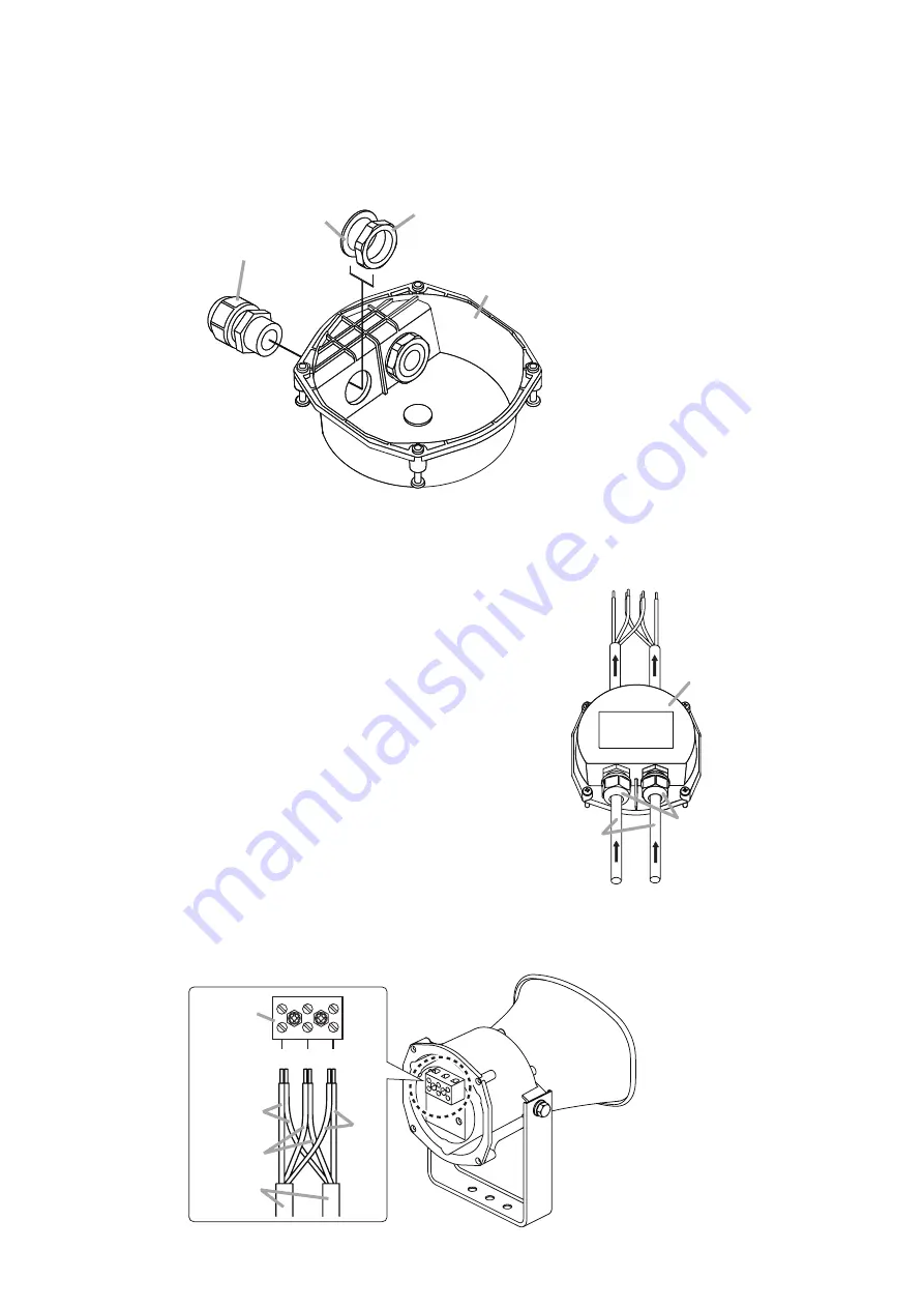
Attach the cable gland to be added.

Notes

• Prepare the cable gland of PG 13.5 size separately.
• Ensure that the cable gland is securely tightened. If loosely tightened, water may get inside the

terminal cover.


Cable gland

Waterproof gasket

Nut

Terminal cover

Step 3.

Strip the speaker cable jacket. (Refer to page 4, Step 1.)

Step 4.

Run one each of speaker cables through the cable gland.

Terminal cover

Speaker cables

Cable glands

4

EARTH HOT COM

COM

HOT

EARTH

Screw
terminal

Speaker
cables

5

Step 5.

Connect the speaker cables with the same polarity to each terminal according to the polarity indication

at the screw terminal.

Summary of Contents for SC-615BS

Page 1: ...7 WIRING DIAGRAM 8 8 FREQUENCY RESPONSE 8 9 SPECIFICATIONS 9 Thank you for purchasing TOA s Paging Horn Speaker Please carefully follow the instructions in this manual to ensure long trouble free use...

Page 2: ...personal injury Avoid installing the speaker near seaside or in locations exposed to corrosive gas The speaker or its parts may be subject to corrosion which might cause it to fall or result in person...

Page 3: ...inless steel bracket for all weather durability The TOA s unique oval shape horn enhances excellent speech clarity Other feature includes a newly developed diaphragm employing special heat resistant p...

Page 4: ...factory preset values LINE VOLTAGE 70V 100V IMP 15W 7 5W 5W 2 5W 1 5W 3W 5W 10W 15W 330 670 OFF 1k 2k 3 3k 4 WIRING The terminal cover is not mounted to the speaker unit when shipped from the factory...

Page 5: ...tep 5 Securely tighten the cable gland Note If loosely tightened water or moisture may get inside the terminal cover Screw Terminal cover 5 Waterproof gasket Screw Cable gland 4 4 2 When Bridge Connec...

Page 6: ...Cable gland Waterproof gasket Nut Terminal cover Step 3 Strip the speaker cable jacket Refer to page 4 Step 1 Step 4 Run one each of speaker cables through the cable gland Terminal cover Speaker cabl...

Page 7: ...pplied screws In this case take care not to pinch the wiring and check that the waterproof gasket is secured into place Note If wiring or the waterproof gasket is pinched between the terminal cover an...

Page 8: ...tching transformer Thermal fuse 84 C or 183 2 F Shown above is the factory default wiring 8 0 25 25 0 98 0 98 141 5 55 36 1 42 126 4 96 172 6 77 130 5 12 229 9 02 104 5 4 11 195 7 68 193 7 6 3 9 0 35...

Page 9: ...One cable gland is factory installed For bridge connection one cable gland can be added Cable Connection Screw terminal Steatite Applicable Cable Size Outer diameter 8 0 12 5 mm Conductor Solid wire o...

Page 10: ......

Page 11: ......

Page 12: ...URL http www toa jp 533 06 244 30...

Reviews: