background image


 Please keep this instruction manual close at hand of the persons who are in charge of 

the operation of this product. 

 Before operating this product, please read this instruction manual carefully for its 

correct handling.


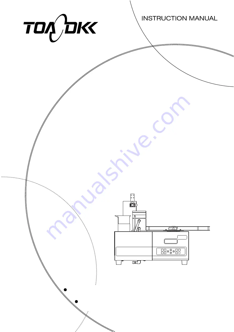
TURN TABLE


MODEL TTT-710


No. TTT-LB16403E


Summary of Contents for TTT-710

Page 1: ... manual close at hand of the persons who are in charge of the operation of this product Before operating this product please read this instruction manual carefully for its correct handling TURN TABLE MODEL TTT 710 No TTT LB16403E ...

Page 2: ...H meter Model HM 30R Model HM 50G Model HM 60G Model HM 42X Conductivity meter Model CM 30R Model CM 40G Model CM 60G Model CM 42X Multi water quality meter Model MM 60R Model MM 43X Automatic titrator Model AUT 701 Model AUT 501 Acidity titrator Model TA 70 Salt titrator Model TS 70 Potentiometric titrator Model TP 70 Automatic burette Model ABT 511 c Since important items are described in Safety...

Page 3: ...rs to burns or electric shock Property damage refers to widespread damage to the home household goods and livestock pets equipment materials etc damage to other than the product itself IMPORTANT Indicates important matters other than and They are the matters such as preventing damage to the product main body preventing data destruction preventing wasting time maintaining performance and observing ...

Page 4: ...an be damaged Caution Label Lost If any caution label affixed to this product becomes too difficult to read or lost please order a new one through your local sales agent or our sales office and affix it to its original position 3 Notes on use of the instruction manual Important items such as Safety compliance items are described in this manual Handle the manual as follows a The instruction manual ...

Page 5: ...ecting equipment not supplied by DKK TOA h Loss of data settings programs or software stored on the product not attributable to DKK TOA i Any product other than DKK TOA s if specified by the purchaser or user that incorporates or is incorporated into or combined with DKK TOA s products 1 In such cases this warranty covers DKK TOA s products only j Any product not under proper maintenance in accord...

Page 6: ...sections to be referred to in sequential order 8 Maintenance and Inspection 9 Troubleshooting 10 Transport Storage Disposal 11 Parts and Option List Purpose Section Start start up Understand the outline of this product Perform respective operations Introduction Safety information 1 Content of Package 2 Specifications and Functions 3 Name and Function of Each Part 4 Preparations 5 Basic Operation 6...

Page 7: ... panel 15 4 Preparations 16 4 1 Installation Preparations 16 4 2 Wiring 18 1 Power cable and ground connections 18 2 Connection to analytical instruments 19 4 3 Piping 25 1 Piping diagram 25 2 Pure water tank connection 26 3 Waste solution tank connection 27 4 4 Table Plate Mounting 30 4 5 Mounting the electrode cartridge electrode and titration nozzle 31 4 6 Optional Parts Connection 35 1 Air pum...

Page 8: ...232C communication conditions setting 67 4 Liquid level sensor alarm setting 68 5 Display contrast setting 69 6 Next specimen preparatory stirring function setting 69 7 Electrode washing conditions setting 70 7 RS 232C Interface 74 7 1 Interface Specifications 74 1 Communication conditions 74 2 Connector and pin arrangement 74 7 2 Message Format 75 1 Receive format PC Turntable 75 2 Send format Tu...

Page 9: ...e solution tank liquid level sensor replacement 99 9 Troubleshooting 101 9 1 Safety precautions when an abnormality occurred 101 9 2 Abnormality by Error Display and Countermeasures 102 9 3 Other Troubles and Countermeasures 104 9 4 System Reset Method 107 10 Transport Storage Disposal 108 10 1 Transport 108 10 2 Storage 109 10 3 Disposal 110 11 Parts and Option List 111 Last page 113 ...

Page 10: ...401560U For 60 specimens 7401570U 1 Electrode cartridge 2 7505010K 1CH cartridge 1 X 7505020K 1CH cartridge 2 X 7506840K 1CH cartridge 3 X 6597970K 2CH cartridge 1 7505030K 2CH cartridge 2 X 6597940K 2CH cartridge 3 6597980K Multi cartridge 6597990K Sample suction cartridge 1 7505010K 1CH cartridge 1 X Pure water tank 10L with liquid level sensor 1 Waste solution tank 10L with liquid level sensor ...

Page 11: ...l Hoffman pinch cock 126C049 1 Power cable 1 3P 2P adapter 3 1 Disposable beaker 200mL 136C179 1 Instruction manual NOTE 1 When the product is purchased any one kind of specified number of specimens table is supplied 2 When the product is purchased any one kind of specified electrode cartridge is supplied 3 3P 2P adapter may not be provided depending on the type of power cable ...

Page 12: ...70 OPTION 2 R Series G Series control input output Automatic burette ABT 511 Flow analysis reference unit FAR 201A control input output External control box control input output Air pump box control output Liquid level sensor signal input washing water 1 waste solution Power output for propeller stirring unit Washing method Standard Pure water shower washing When options attached Pure water bubbli...

Page 13: ...ax Approx 90VA when 240VAC used When options connected Max Approx 100VA when 100VAC used Max Approx 130VA when 240VAC used Main body dimensions Dimensions when table plate not mounted Approx 440 W 409 H 391 D mm Dimensions when table plate mounted Approx 566 W 409 H 507 D mm Max dimensions when operating Approx 566 W 534 H 507 D mm Main body weight Approx 16kg when table plate not mounted Approx 1...

Page 14: ...mode Conditions setting Measurement start table No 1 to number of specimens of each table plate Measurement end table No 1 to number of specimens of each table plate and endless Number of repetitive measurement 1 to 9 times Stirring time before measurement 0 to 9999 seconds Wait time before measurement 0 to 9999 seconds End buzzer time 0 to 9999 seconds RS 232C interface Standard equipment Communi...

Page 15: ...se for overflow port Waste solution hose for outlet 1 Left side Power switch power ON power OFF Electrode arm Top side Table plate End detection pin Back side RS 232C connection connector RS 232C Air pump box connection connector TO AIR PUMP Liquid level sensor connection connector for pure water LEVEL ALARM RINSE 1 Power inlet with fuse 100 240V 130VA FUSE F4AH250V Liquid level sensor connection ...

Page 16: ...onditions setup and manual washing operation screen SIGNAL key SIGNAL Switches to each operation signal confirmation screen STIRRER key STIRRER Starts or ends manual stirring operation SET key SET Switches to the setup screen of each measurement condition ENTER key ENTER Enters each condition set value Performs manual washing or each operation signal confirmation Up and down keys Changes values in...

Page 17: ... W 584 H 557 D mm When using with G Series analytical instruments 948 W 584 H 557 D mm When using with Automatic Titrator AUT 701 including Titration Burette ABT 7 1 unit 1076 W 584 H 557 D mm When using with Automatic Titrator AUT 501 including Titration Burette ABT 511 1 unit 1126 W 584 H 557 D mm When using with dedicated Titrator TA 70 TS 70 or TP 70 876 W 584 H 557 D mm When using with Automa...

Page 18: ...Model TTT 710 4 1 Installation Preparations 17 918 Provide an empty space of 100mm or more Example of Installation Combined with R Series Analytical Instruments ...

Page 19: ...he plug at the other end of the power cable to an AC power outlet Power Cable and Ground Connections b When the power plug cannot be connected to 3 pin outlet connect the accessory 3P 2P adapter to the power cable and connect it to an AC power outlet Also connect the 3P 2P adapter ground wire to a ground line When accessory 3P 2P adapter is provided AC power outlet 3P 2P adapter Power cable Produc...

Page 20: ...nts HM 50G others Automatic titrator AUT 701 4 2 2 e Connection to automatic titrator AUT 701 Automatic titrator AUT 501 4 2 2 f Connection to automatic titrator AUT 501 Acidity titrator TA 70 4 2 2 g Connection to dedicated titrator TA 70 others Salt titrator TS 70 Potentiometric titrator TP 70 Automatic burette ABT 511 4 2 2 h Connection to automatic burette ABT 511 Flow analysis reference unit ...

Page 21: ...tor RS 232C Left side RS 232C connection connector R Series analytical instruments HM 30R CM 30R MM 60R Product main body Back side Connecting to R Series Analytical Instruments HM 30R others RS 232C connection c Connection to R Series analytical instruments HM 30R others OPTION2 connection Connect the R G Series connection connector of product main body and the external connection connector OPTIO...

Page 22: ...N 2 of G Series analytical instruments HM 50G others using the OPTION 2 connection cable optional Connecting to G Series Analytical Instruments HM 50G others e Connection to automatic titrator AUT 701 Connect the RS 232C connection connector of product main body and the TTT 510 connection connector of automatic titrator AUT 701 using the turntable connection cable optional Connecting to Automatic ...

Page 23: ...GC00006 Back side TTT 3100 connection connector TTT 3100 Automatic titrator AUT 501 RS 232C connection connector RS 232C Back side Product main body Connecting to Automatic Titrator AUT 501 g Connection to dedicated titrator TA 70 others Connect the RS 232C connection connector of product main body and the TTT 510 connection connector of dedicated titrator TA 70 others using the turntable connecti...

Page 24: ...ette ABT 511 using the ABT 511connection cable optional Connection to Automatic Burette ABT 511 i Connection to flow analysis reference unit FAR 201A Connect the ABT FAR connection connector of product main body and the EXT and EXT connection connector of flow analysis reference unit FAR 201A using the FAR connection cable optional Connecting to Flow Analysis Reference Unit FAR 201A ...

Page 25: ... and the PC connector using a suitable cable straight type b When the PC uses a D sub 9 pin connector RS 232C cable part No 0GC00002 is available as a DKK TOA option If the PC does not have RS 232C port purchase and use USB RS232C adapter manufacturer MOXA Part code UPort 1150I as a recommended part RS 232C straight cable etc To PC side connector PC RS 232C connection connector RS 232C Back side P...

Page 26: ...es are optional specifications Waste water valve Air blow Overflow Air bubbling Drain Washing reservoir Air pump box Pure water tank Waste solution tank Pure water pump Product back side Liquid level sensor connection connector for waste solution LEVEL ALARM DRAIN Liquid level sensor connection connector for pure water LEVEL ALARM RINSE1 Piping Diagram ...

Page 27: ...e cutters etc to cut the accessory washing water tube part code 116E049 to a suitable length matching the distance between the IN side of the pure water pump at the front of the main body and the pure water tank to be installed and use the tube as the washing water tube for pump Pass the tube through O ring Pass one end of the washing water tube for pump prepared at step through the accessory O ri...

Page 28: ...duct main body and the waste solution tank to be used and use the hose as the waste solution hose for outlet 2 Connect the waste solution hose Connect one end of the waste solution hose for outlet 2 prepared at step to waste solution outlet 2 of product main body and the other end to the waste solution tank piping port IMPORTANT Install the waste solution tank at a place sufficiently lower than th...

Page 29: ... 1 Waste solution hose for outlet 2 Waste solution tank Piping port Connecting the Waste Solution Hose for outlet 2 Correct Method of Piping the Waste Solution Hose Insert the plug Insert the plug of the liquid level sensor into the liquid level sensor connection connector for waste solution of the product main body ...

Page 30: ...el sensor connection connector for waste solution LEVEL ALARM DRAIN Back side Plug Waste solution tank Waste solution hose for outlet 2 Liquid level sensor for waste solution Inserting the Plug of the Liquid Level Sensor for waste solution ...

Page 31: ... main body table holder plate Top side Table plate Pins 3 places Table holder plate Holes 3 places Product main body Setting the Table Plate on the Table Holder Plate Fix the table plate Fix the table plate by tightening the table plate fixing cap nut connected to the end detection pin from the top of the table plate Fix the end detection pin Fix the end detection pin to the end detection pin hold...

Page 32: ...t main body hold the electrode cartridge with the dent facing upward and insert the cartridge into the end of the electrode arm and fix it by tightening the knurled knob Mount the electrode and titration nozzle Loosen the electrode fixing bolt of the electrode cartridge insert the electrode and titration nozzle to be used and fix the electrode by tightening the electrode fixing bolt The electrode ...

Page 33: ...7505030K 12 specimens 18 specimens 36 specimens X R J white adapter use ION silver adapter use 2CH cartridge 3 Electrode 2 Nozzle 2 6597940K 12 specimens 18 specimens X R J white adapter use ION silver adapter use Multi cartridge Electrode 4 Nozzle 4 6597980K 12 specimens J max 2 ION 2 Up to 4 can be mounted by using the silver adapter Sample suction cartridge Nozzle 1 6597990K All number of speci...

Page 34: ...1C GST 5722S ORP composite electrode PST 5821C GST 5723S Conductivity cell CT 58101B GST 5724C CT 58101C GST 5725C ELC 009 GST 5726S ELC 010 ORP composite electrode PST 5721C Electrode type J Electrode type ION Name Model Name Model Name Model pH composite electrode GST 5731C Silver composite electrode ELX 006 Chloride ion electrode CL 125B GST 5711C Comparison electrode HS 305D pH glass electrode...

Page 35: ...re Sensors Table Nozzle Temperature sensor Name Model Name Model Degassing nozzle 1 to 20mL P000070 Temperature sensor general purpose SUS ELT 001 Degassing nozzle 50mL P000071 Temperature sensor general purpose glass ELT 002 Titration nozzle micro volume AST P008 Temperature sensor TH 1005B Suction nozzle P000035 ...

Page 36: ...sold separately must be installed i When using the air pump box air blowing only Cut the tube Cut the tube from the air pump box to a suitable length using cutters etc Connect the tube Connect the end of the tube from the air pump box to the washing reservoir air connection port of the product main body Connecting the Tube to the Air Pump Box Connect the cable Connect the air pump connection conne...

Page 37: ...r Pump Box Remove the blank tube After turning the set screw and removing the blank tube from the washing reservoir remove the set screw and ferrule from the blank tube Connect the Bubbling Washing Tube to Air Pump Box Connect the bubbling washing tube Pass the end of the bubbling washing tube through the set screw and ferrule removed at step and connect the tube to the washing reservoir IMPORTANT...

Page 38: ...Air Pump Box 2 Waste water valve connection a When performing electrode bubbling washing use the waste water valve optional to collect the washing water at the washing reservoir b When performing bubbling washing with pure water or when the waste solution contains sludge use a pinch cock type waste solution valve 7401650U c When performing bubbling washing with liquid chemical use the solenoid typ...

Page 39: ...oir Power switch Magnet catch 2 places Removing the Drain Pipe and Blank Panel Remove the blank panel Loosen the 4 screws and remove the blank panel Insert the connector plug Pass the waste water valve connector plug into the product main body through the hole left by removing the blank panel and insert the plug into the internal connector receiver CN9 Inserting the Waste Water Valve Connector Plu...

Page 40: ...iping the Waste Water Valve 3 Propeller stirring unit connection Use the propeller stirring unit optional when stirrer stirring by stirring bar is impossible because the viscosity of the measured solution is high or some other reason Install the propeller stirring unit After loosening the knurled knob at the end of the electrode arm of the product main body insert the propeller stirring unit at th...

Page 41: ...trode washing is performed with a liquid other than pure water the optional reagent washing kit must be used When handling the liquid chemical procure the Safety Data Sheet SDS for the reagent to be handled from the vendor and wear suitable protective gear and handle the chemical safely in accordance with the description The liquid chemical washing kit consists of the following Reagent washing res...

Page 42: ...ump box Reagent pump Pure water pump Waste water valve Air blow Reagent washing Pure water washing Overflow Air bubbling Drain TTT back side EXT SIG BOX TO AIR PUNP Reagent washing reservoir Note The dotted lines are optional ii External signal box connection Never place articles on top of the external signal box Install the external signal box as far away from water as possible ...

Page 43: ... 3P 2P adapter Power cable Product side plug Ground wire Ground line Back side External signal box Power plug Product side plug Power cable Power inlet AC power outlet For 3P outlet iii Reagent pump and reagent tank connection Fill the reagent tank at least half full of the washing water to be used Cut the washing water tube PTFE tube supplied to the following lengths using cutters etc Between rea...

Page 44: ...agent pump Pulse suppressor Washing water tube PTFE tube Washing water tube PTFE tube Reagent washing reservoir Reagent tank Liquid level sensor Connect the power connector of reagent pump to TO RINSE PUMP of the external signal box and insert the liquid level sensor plug of the reagent tank into LEVEL ALARM RINSE 2 of the external signal box ...

Page 45: ...the front side of main body Front side Waste solution hose Connect the other end of the waste solution hose to the piping port of the waste solution tank Install the waste solution tank at a position sufficiently lower than the turntable main body Also be sure that the waste solution hose is straight from top to bottom If the hose is bend midway between top and bottom the waste solution will colle...

Page 46: ... the liquid level sensor into LEVEL ALARM DRAIN on the back side of the main body Liquid level sensor connection connector for waste solution LEVEL ALARM DRAIN Back side Plug Waste solution hose for outlet 2 Liquid level sensor for waste solution Waste solution tank ...

Page 47: ...ENTER ENTER Arm movement Table plate rotation Washing end ENTER No setting Sequence selection Value setting Item selection START STOP based on the analytical instrument side operations based on the product side operations All measurements end All measurements end Measurement starts by analytical instrument ENTER Continued to 2 3 Arm movement Arm movement Stirring speed adjustment TABLE WASH WASH E...

Page 48: ... Screens Map 47 SIGNAL SIGNAL ENTER Item selection ENTER ENTER ENTER ENTER ENTER ENTER ENTER ENTER ENTER ENTER ENTER ENTER ENTER ENTER ENTER ENTER ENTER ENTER ENTER ENTER ENTER ENTER Continued to 3 3 ENTER ENTER ENTER ENTER ENTER ...

Page 49: ...Model TTT 710 5 1 Operation Screens Map 48 ENTER Item selection ENTER ENTER ENTER ENTER ENTER ENTER ENTER ENTER ENTER ENTER ENTER SET SET Operation Screens Map 3 3 ...

Page 50: ...tch of automatic burette and flow analysis reference unit to ON last of all ⓐ Turn on this product Set the power switch at the left hand side of the product main body to ON After the Opening screen is displayed for 1 second and initial operations of electrode arm and table plate rotation are performed the Measurement Waiting screen is displayed Opening screen Measurement Waiting screen ⓑ Turn on t...

Page 51: ...rement begins based on the analytical instrument side operations During continuous measurement the sequence operation currently being performed is displayed During continuous measurement product main body key operations other than stirring speed adjustment during stirring are ineffective Measuring screen arm moving Effective operations during measurement The following operations can be performed d...

Page 52: ...ing Sample measurement conditions Measurement start stop table No stirring time waiting time before measurement number of repetitive measurements and end buzzer time ⓓ Set the analytical instrument side conditions Set the connection mode to OPTION2 and turntable measurement to ON Instruction manual of analytical instrument to be used Set the measurement specimens 5 2 1 a Measurement preparations P...

Page 53: ... Cancel screen is displayed 1 When measurement of table No with end detection pin inserted is ended 2 When measurement of the end table No set at the product is ended 3 When START STOP of the product main body is pressed When continuous measurement ends the electrode arm moves to the washing reservoir and after the electrode washing operation is performed the electrode arm moves to the electrode s...

Page 54: ...ⓓ Set the RS 232C communication conditions 6 2 Various Conditions Setting 3 RS 232C communication condition setting Set the measurement specimens 5 2 1 a Measurement preparations Prepare the end detection pin 5 2 2 a Measurement preparations b Continuous measurement from start to end Operation Procedure Operation Screen example Display the Measurement Waiting screen Confirm that the Measurement Wa...

Page 55: ...ing during end processing Measurement Cancel screen 4 Use by connecting automatic burette ABT 511 When using this product by connecting it to an automatic burette ABT 511 setup measurement start stop and other operations are performed based on the product side operations a Measurement preparations Set the power switch to ON 5 2 1 a Measurement preparations Always turn on the power switches in orde...

Page 56: ...erations can be performed during continuous measurement When the or key is pressed during stirring operation the stirring speed can be adjusted Continuous measurement can be stopped 3 Measuring screen stirring operating Measurement end Continuous measurement ends in any of the cases 1 to 3 below and Measurement Cancel screen is displayed 1 When measurement of table No with end detection pin insert...

Page 57: ...operation on off and speed adjustment can also be performed linked with arm movement at this screen Operation Procedure Operation Screen example To the Arm Operating screen stirring off Press ARM at the Measurement Waiting screen Arm Operating screen stirring off Move the arm Move the arm by the following key operations at the Arm Operating screen stirring off Up Down Moves to the right electrode ...

Page 58: ...e plate and lowers it Stop the stirring operation When STIRRER is pressed again stirring stops and the display returns to the step screen End the arm operation Press ARM at the step screen The arm moves to the electrode storage beaker and operation ends After stirring stops operation can be ended the same as mentioned above even if ARM is pressed at the step screen In any case the display returns ...

Page 59: ...te Operating screen stirring off Rotate the table plate to a specific table No Press SET at the step screen The Movement Table No Setting screen appears Set the table No and rotate the table plate to that number by the following key operations Increments the set value Decrements the set value ENTER Rotates the table plate and moves to the set table No then returns to the step screen When the stirr...

Page 60: ... the electrode storage beaker and the table moves to the home position and operation ends After stirring stops operation can be ended the same as mentioned above even if TABLE is pressed at the step screen In any case the display returns to the Measurement Waiting screen 3 Stirring operation and speed adjustment Use the Stirring Operating screen when performing only the stirring operation by key o...

Page 61: ...er closing the waste water valve and collecting the pure water in the washing reservoir by pure water pump operates the bubbling switching valve and air pump in the air pump box 8 RINSE2 SHOWERING Reagent Shower Operating screen Executes the liquid chemical shower washing sequence Operates the liquid chemical pump 9 RINSE2 BUBBLING Reagent Bubbling Operating screen Executes the liquid chemical bub...

Page 62: ...rates the air pump 4 BUBBLING PUMP Operates the bubbling switching valve and air pump 5 DRAIN VALVE Closes the waste water valve Start operation Press ENTER at the step screen The Operating screen of the operation signal selected at step appears and operation starts Pure Water Pump Operating screen Reset the operation signal Press ENTER during each operation Pump operation stops Waste water valve ...

Page 63: ...ion signal Press ENTER during each operation At pure water shower washing the pure water pump stops At reagent shower washing the reagent pump stops At pure water bubbling washing the bubbling switching valve and air pump stop and the waste water valve opens At reagent bubbling washing the bubbling switching valve and air pump stop and the waste water valve opens At pure water soak washing the was...

Page 64: ...EMPTY is displayed and an alarm is sounded If the liquid level of the waste solution tank is abnormal FULL is displayed and an alarm is sounded When liquid level is normal When liquid level is abnormal Reset the operation signal Press ENTER during each operation Returns to the step screen after any operation End the checking Press SIGNAL The display returns to the Measurement Waiting screen When a...

Page 65: ...g screen is displayed automatically The electrode arm movement table rotation stirring and re washing operations can be performed at this screen Arm up When this key is pressed again while the arm is at the topmost position the arm moves to the left or right Note When the arm is washing reservoir position it moves to the right When the arm is in the table position it moves to the left Arm down Tab...

Page 66: ...lay Contrast Adjustment screen Adjusts the display contrast brightness 6 Next No Stir Set Next Specimen Preparatory Stirring Setting screen Sets On Off of the next specimen preparatory stirring function option b There is the 1 electrode washing condition item of the table shown below The setting can be changed from the Electrode Washing Selection screen Electrode Washing Conditions Item and Settin...

Page 67: ...e No Table No at which continuous measurement is to end When measurement of the specimen of the set table No or with the end detection pin inserted ends continuous measurement ends When set to 0 continuous measurement ends only at the end detection pin Repeat Times Number of measurement repetitions Number of times the same specimen is to be measured repeatedly Stirring Time Stirring time before me...

Page 68: ... value last digit Change the value ENTER Enters the set value After setting the display returns to the Condition Setting Item Selection screen Cursor blinking Measurement Condition Setting screen End the setting Press SET The display returns to the Measurement Waiting screen 3 RS 232C communication conditions setting a When the product is operated by analytical instrument and RS 232C control or wh...

Page 69: ...ss SET The display returns to the Measurement Waiting screen 4 Liquid level sensor alarm setting The liquid level sensor function of pure water tank Rinse1 reagent tank Rinse2 and waste solution tank DRAIN can be turned ON or OFF Setting Procedure Operation Screen example To the Conditions Setting Item Selection screen Press SET at the Measurement Waiting screen Condition Setting Item Selection sc...

Page 70: ...display returns to the Condition Setting Item Selection screen Display Contrast Adjustment screen End the setting Press SET The display returns to the Measurement Waiting screen 6 Next specimen preparatory stirring function setting The next specimen preparatory stirring function optional specification can set whether or not the next measurement specimen is to be pre stirred The number of table spe...

Page 71: ...n this product is connected to the following analytical instruments the conditions set here become effective R Series analytical instruments by OPTION2 connection G Series analytical instruments Acidity titrator TA 70 Salt titrator TS 70 Potentiometric titrator TP 70 Automatic burette ABT 511 During manual washing operation c When this product is connected to the following analytical instruments t...

Page 72: ...creen Display and Item Names and Washing Contents Setting screen item display Washing item name Washing operation contents Rinse1 Showering Pure water shower Performs pure water shower washing Rinse1 Bubbling Pure water bubbling Collects pure water at the washing reservoir and performs air bubbling washing Rinse2 Showering Reagent shower Performs reagent shower washing Rinse2 Bubbling Reagent bubb...

Page 73: ...the cursor blinking to the value last digit of the setting item Change the value ENTER Enters the set value After setting the display returns to the Electrode Washing Selection screen Cursor blinking Washing Detail Condition Setting screen End the setting Press WASH The display returns to the Measurement Waiting screen Setting Procedure Washing Mode No 9 Operation Screen example To the Electrode W...

Page 74: ...ad of the washing item the type of washing item is switched If the cursor is over the washing time over the air blow number of times the value of the last digit the value is increased or decreased If you want to end washing order at 4 th within the next washing order select the Wash End in the washing item incidentally ENTER Enters the set value After setting the display returns to the Electrode W...

Page 75: ...elected from 7 or 8 bits Parity Selected from among none odd even Stop bit Selected from 1 or 2 bits The factory settings are 4800 bps start 1 bit data length 8 bits no parity stop 2 bits 2 Connector and pin arrangement The connector used is D sub 9 pins male connector Pin No Signal symbol Signal name Direction 1 No Connection 2 SD TXD Send data Input 3 RD RXD Receive data Output 4 No Connection D...

Page 76: ... No and upper propeller simultaneous stirring KA1 Standard table outer periphery only stirring 100 specimens specifications Outer periphery only stirring KA2 Standard table inner periphery only stirring 100 specimens specifications Middle periphery only stirring KA3 Upper propeller stirring KA4 Next specimen stirring table outer periphery only stirring 100 specimens specifications Inner periphery ...

Page 77: ...F Identification code TO fixed Table No 001 to100 When the arm is lower than the measurement beaker position the table is moved after the arm is raised After the end of operation an operation end command M command is sent from the turntable Washing mode operation execution WC1CRLF Identification codes WC1 Washing mode 1 operation WC2 Washing mode 2 operation WC3 Washing mode 3 operation WC4 Washin...

Page 78: ...bling WS3 Reagent shower WS4 Reagent bubbling WS5 Pure water soak WS6 Reagent soak Washing ON OFF 1 ON 2 OFF When ON other operation commands cannot be executed An error command is sent from the turntable Pump and waste water valve ON OFF PM1 1CRLF Identification codes PM1 Waste water valve operation PM2 Air pump 3 way solenoid valve operation air bubbling operation PM3 Reagent pump operation PM4 ...

Page 79: ...tion ON OFF 1 OFF 2 ON When ON other operation commands cannot be executed An error command is sent from the turntable ABT 511 dispensing operation ABTCRLF Identification code ABT fixed After the end of operation an operation end command M command is sent from the turntable c Operation conditions setting Washing mode No setting WA1CRLF Identification codes WA1 Washing mode 1 WA2 Washing mode 2 WA3...

Page 80: ...WM2 xxxx xxxx xCRLF Identification code WM2 fixed Pure water bubbling time 0000 to 9999 Pure water shower time 0000 to 9999 Number of air blows 1 to 9 Washing mode 3 WM3 xxxx xxxx xCRLF Identification code WM3 fixed Reagent shower time 0000 to 9999 Pure water shower time 0000 to 9999 Number of air blows 1 to 9 Washing mode 4 WM4 xxxx xxxx xCRLF Identification code WM4 fixed Reagent bubbling time 0...

Page 81: ...d Reagent bubbling time 0000 to 9999 Reagent shower time 0000 to 9999 Number of air blows 1 to 9 Washing mode 7 WM7 xxxx xCRLF Identification code WM7 fixed Reagent shower time 0000 to 9999 Number of air blows 1 to 9 Washing mode 8 WM8 xxxx xxxx xxxx xCRLF Identification code WM8 fixed Reagent bubbling time 0000 to 9999 Pure water bubbling time 0000 to 9999 Reagent shower time 0000 to 9999 Number ...

Page 82: ...ng contents of the washing item in 0 Washing end 1 Pure water shower 2 Pure water bubbling 3 Reagent shower 4 Reagent bubbling 5 Air blow 6 Pure water immersing 7 Reagent immersing In the 1 4 th of washing item 0 if the washing end has been set it will not run washing item that are set to it after Time of washing item in number of times in the case of air blow setting range In the case of washing ...

Page 83: ... ON OFF setting KM xCRLF Identification code KM fixed Setting ON OFF 1 ON 2 OFF d Set value and status requests Various set value current table No and end pin detection requests QS01CRLF Identification code QS01 Stirring time before measurement QS02 Waiting time before measurement QS03 Number of table specimens QS04 Tank liquid level sensor status pure water reagent and waste solution QS05 Current...

Page 84: ...request command of stirring time before measurement was received QS01 xxxxCRLF Identification code QS01 Stirring time before measurement 0000 to 9999 When request command of waiting time before measurement was received QS02 xxxxCRLF Identification code QS02 Waiting time before measurement 0000 to 9999 When request command of number of table specimens was received QS03 xxxCRLF Identification code Q...

Page 85: ... was received QS05 xxxCRLF Identification code QS05 Current table No 001 to 100 When request command of end pin detection status was received QS06 xCRLF Identification code QS06 End pin detection status 0 End pin not detected 1 End pin detected When request command of washing mode No was received Washing mode 1 QW1 xxxx xCRLF Identification code QW1 Pure water shower time 0000 to 9999 Number of ai...

Page 86: ... to 9999 Pure water shower time 0000 to 9999 Number of air blows 1 to9 Washing mode 5 QW5 xxxx xxxx xxxx xCRLF Identification code QW5 Reagent bubbling time 0000 to 9999 Pure water bubbling time 0000 to 9999 Pure water shower time 0000 to 9999 Number of air blows 1 to9 Washing mode 6 QW6 xxxx xxxx xCRLF Identification code QW6 Reagent bubbling time 0000 to 9999 Reagent shower time 0000 to 9999 Num...

Page 87: ...rd washing item 0to7 Time of the 3rd washing item 0000to9999 Number of times in the case of air blow 0001to0009 The 4th washing item 0to7 Time of the 4th washing item 0000to9999 Number of times in the case of air blow 0001to0009 The 5th washing item 0to7 Time of the 5th washing item 0000to9999 Number of times in the case of air blow 0001to0009 The contents of the washing item in 0 Washing end1 Pur...

Page 88: ...ays verify that the power is off before connecting or disconnecting the power cord plug and the plug of various cables Water or chemicals entering the product may short the circuits and cause electric shock or fire Waterproofing and drip proofing This product does not have a waterproof or drip proof construction Do not touch the product with wet hands or wash it with water Also do not install or s...

Page 89: ...hat there is sufficient washing water to perform continuous measurement When the washing water level is low add water 2 Piping tube deterioration damage bending If the piping is deteriorated damaged or bent replace it 8 3 2 Washing water tube replacement 3 State of water supply to washing reservoir pump operation Operate the pure water pump and check the state of discharge of the washing water 6 1...

Page 90: ...sor does not function normally replace it 8 7 Liquid Level Sensor Replacement 9 Storage reservoir Electrode storage beaker pure water level Check if the water level is sufficient to immerse the end of the electrode and nozzle installed to the end of the electrode arm If the water level is low add pure water 10 Electrode arm Up and down operation Check that there is no abnormal sound when the arm m...

Page 91: ...een pure water tank piping port to pure water pump IN side Washing water tube for washing reservoir Between pure water pump OUT side to washing reservoir pure water supply port Pure water tank Pure water pump Washing reservoir Front side Piping cover Pure water supply port Liquid level sensor for pure water Washing water tube for tank Washing water tube for washing reservoir Washing water tube for...

Page 92: ...e front left hand side of the product Remove the old tubes Of the washing water tube for tank washing water tube for pump and washing water tube for washing reservoir remove the tube that requires replacement Washing Water Tube Replacement Replace the tube Cut the new washing water tube part code 116E049 to the length of the tube removed at step and install it as it was originally 4 3 2 Pure water...

Page 93: ... pure water pump If the inside of the product is touched in the energized state there is the danger of electric shock In addition do not work with wet hands Water or reagent entering the product may short the circuits and cause electric shock or fire Pure Water Pump Replacement Set the power switch to OFF Set the power switch at the left hand side of the product to OFF Remove the piping cover Remo...

Page 94: ...roduct Also disconnect the pure water pump lead wire connector terminal Remove the pure water pump Loosen the fixing screws 4 screws and remove the pure water pump from the mounting plate Replace the pure water pump Fix the new pure water pump to the mounting plate in the original direction Connect the lead wire Connect the pure water pump lead wire to the connector terminal board inside the produ...

Page 95: ...nd check that the following waste solution hoses 3 hoses are not deteriorated damaged or bent Especially check that there is no floating up at the waste solution hose for outlet 2 If there is a problem replace the waste solution hose 8 4 2 Waste solution hose replacement Waste solution hose for outlet 1 Between washing reservoir waste solution outlet 1 and waste solution block Waste solution hose ...

Page 96: ...ver Remove the piping cover on the front left hand side of the product Remove the old hose Of waste solution hose for outlet 1 waste solution hose for overflow port and waste solution hose for outlet 2 remove the hose that requires replacement Waste Solution Hose Replacement Replace the hose Cut the new waste solution hose to match the length of the old waste solution hose for outlet 1 for outlet ...

Page 97: ...d such as application of a load on the elevator shaft or that TIME OVER ERROR is not displayed Arm up and down operation 6 1 1 Arm movement and stirring operation b If an abnormal sound is generated or a TIME OVER ERROR is displayed contact DKK TOA or you sales representative 2 Electrode arm position inspection and adjustment a Move the electrode arm in the left to right direction swing and when t...

Page 98: ...t the electrode arm is at the center position fix the arm by retightening the set screws 2 places with the hexagonal wrench as they were originally Adjust the front to back direction position Using a hexagonal wrench 2mm loosen the arm upper screws 2 places and free fixing of the arm front to back direction Next after adjusting the arm by blocks in the front to back direction so that the electrode...

Page 99: ...or of the pure water tank from the liquid level connection connector for pure water LEVEL ALARM RINSE1 on the back side of the product Removing the Plug and Tube of Liquid Level Sensor for pure water Disconnect the tube Disconnect one end of the washing water tube for pump from the piping port of the pure water tank Replace the liquid level sensor Loosen and remove the pure water tank cap and remo...

Page 100: ... level connection connector for pure water LEVEL ALARM RINSE1 2 Waste solution tank liquid level sensor replacement Waste solution hose for outlet 2 Waste solution tank Piping port Plug Washing reservoir Front side Piping cover Back side Liquid level sensor connection connector for waste solution LEVEL ALARM DRAIN Waste solution outlet 2 Liquid level sensor for waste solution Removing the Plug and...

Page 101: ...ping port Replace the liquid level sensor Loosen and remove the waste solution tank cap and remove the old liquid level sensor from the tank Insert the new liquid level sensor into the waste solution tank and fix it by tightening the cap as it was originally Waste solution tank Liquid level sensor for waste solution Waste solution hose for outlet 2 Remove Cap Lead wire Piping port Replacing the Li...

Page 102: ...d pull the power plug from the outlet Since there may be a fire or the interior may be damaged in these cases contact your sales representative or DKK TOA Never use the product in an abnormal state It will cause a fire or electric shock Never disassemble and repair the product by yourself because it is extremely dangerous Waterproofing and drip proofing This product does not have a waterproof or d...

Page 103: ...iquid level sensor Liquid level sensor is not connected Connect the liquid chemical liquid level sensor Invalidate the liquid level sensor alarm setting 4 Liquid level sensor alarm setting in 6 2 Various Conditions Setting DRAIN FULL Checked DRAIN Tank Waste solution tank liquid level over error Waste solution tank is full of waste solution Empty the waste solution tank Waste solution tank liquid ...

Page 104: ... operation motor error Alarm left right operation motor is abnormal Contact DKK TOA or your sales representative Table motor error Table operation motor error Table rotation operation motor is abnormal Contact DKK TOA or your sales representative Arm up and down overrun error Arm up down operation overrun error The arm exceeded the limit at arm up down operation Turn the power off and on and check...

Page 105: ...parts 2 Waste solution hose replacement in 8 4 Waste Solution Flow Passage Maintenance and Inspection Air locked inside the waste solution tank Pipe the waste solution hose straight down to the waste solution tank 3 Waste solution tank connection in 4 3 Piping Liquid is leaking from the tubing Tube or joint parts are damaged Replace the damaged tube or joint parts RINSE1 EMPTY Checked RINSE1 Tank ...

Page 106: ...iring The display of this product is not READY display Make the display of this product READY Measurement Waiting screen Continuous measurement is not ended by the specimen in which end detection pin is inserted End table No setting is lower than the table No with inserted end detection pin Set the set value of end table No to the maximum number of table specimens or to 0 endless 2 Measurement con...

Page 107: ... 4 6 Optional Parts Connection Reagent pump does not operate at reagent shower washing External signal box is not connected to the product main body Connect the external signal box 4 Reagent washing kit connection in 4 6 Optional Parts Connection External signal box power cable is not connected Connect the power cable 4 Reagent washing kit connection in 4 6 Optional Parts Connection External signa...

Page 108: ... switch to OFF Set the power switch at the left hand side of the product to OFF Perform system reset While pressing ENTER and simultaneously set the power switch to ON When the Initialize screen appears release the fingers from 2 keys System reset is performed After the Initialize screen is displayed for 1 second the display switches to the Opening screen and then initial operation is performed an...

Page 109: ...he power and pull the power plug from the outlet When carrying and transporting the product always remove the table plate from the main body and transport them separately When carrying and transporting the product always remove the piping cover from the main body If the product is carried with the piping cover installed the piping cover may fall off during transport or main body may fall off and b...

Page 110: ...ation A location where corrosive gases are not present A location without condensation A location where direct sunlight does not strike A location where vibration does not exist A location with little dust and dirt A location where the product is not directly exposed to the wind from air conditioning equipment A location away from stoves and other heating equipment A location with a sense of stabi...

Page 111: ... When disposing of the product or reagent process it based on local regulations For details consult your local authorities Explosion and fire Do not place the product in a fire or burn it Doing so may cause an explosion or fire inside the product ...

Page 112: ...rtridge 2 6597990K 1 10L tank TTT P001 1 Liquid level sensor for pure water 7401610U 1 Liquid level sensor for waste solution 7401620U 1 Unitube 3W 116E049 1m Piping between washing water pure water tank and pure water pump Braided hose ϕ12 18 XD701500 1m Piping between washing block drain port waste solution tank End detection pin 7401630U 1 AC power cord 118C025 1 Plug A type Max 125VAC AC power...

Page 113: ...cable 7075670K 1 For AUT 701 TA 70 TS 70 TP 70 connection cable length 2m RS232C cable 2m 0GC00006 1 For AUT 501 connection cable length 2m TTT connection 232C cable 2m cross 118C087 1 For R Series RS 232C connector connection OPTION2 connection cable 7401740K 1 For G Series R Series OPTION2 connector connection Turntable connection RS232C cable 7433040K 1 For X Series connection ABT 511 connectio...

Page 114: ...Instruction Manual No TTT LB16401E 19 01 2015 JJ New Version in English RSL Katou DEC Kuribayashi LB16402E 18 05 2016 DEC RSL Katou DEC Shimura LB16403E 09 06 2017 DEC RSL Katou DEC Shimada Print size B5 Original size A4 Perfect bind RSL ...

Page 115: ... 114 ...

Page 116: ... 115 品 質 保 証 責 任 者 之 印 We certify that product has tested in the company s standard and passed この製品が当社の厳密な検査に合格し 製品仕様を満足していることを証明します 製 品 合 格 証 TEST CERTIFICATE ...

Page 117: ... 116 ...

Page 118: ...Head Office Address 29 10 1 Chome Takadanobaba Shinjuku Ku Tokyo 169 8648 Japan Telephone 81 3 3202 0225 Facsimile 81 3 3202 5685 URL http www toadkk co jp ...

Reviews: