

Summary of Contents for TTT-710
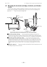
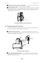
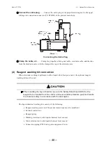
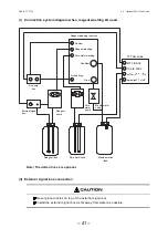
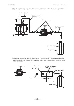
Page 115: ... 114 ...
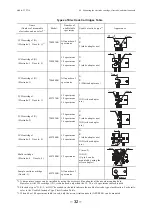
Page 117: ... 116 ...
The Toa TTT-710 Instruction Manual is readily available for download - completely free of charge - from our website. This comprehensive manual provides step-by-step instructions for optimal use of your Toa TTT-710, ensuring you get the most out of its features and functionalities.
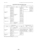
Page 115: ... 114 ...
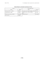
Page 117: ... 116 ...