10-12
Rigging
r/min
TLDI 75/90C2 2010
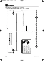
9.
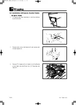
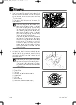
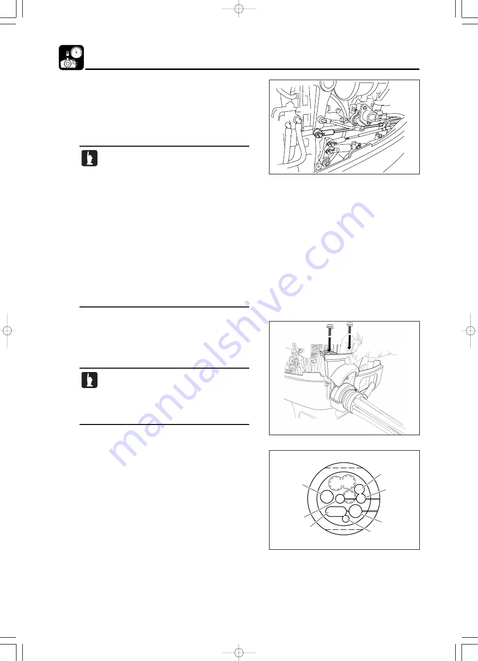
Run cord ass’y, hose and control cables through their
specified holes of the cord grommet, secure them using
cord clamps, and attach hose clamp to secure the cord
grommet as shown.
a
e
c
g
d
b
f
Before securing hose clamp, check that the hoses
and cords are put surely in their specified holes.
If they are put in the holes improperly, the hoses
may collapse, and cord clamp cannot be attached
to the lower cowl.
8.
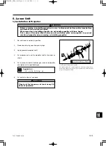
Adjust screw in length of cable joint so that cable joint hole
aligns with shift arm and advancer arm pins, lock the joint
with nut, and then, set it on the arm pin and secure with
“R” pin and washer.
Put the cable in cable clip groove, and then secure it by
using cord clamp.
Check that shifting control lever forward (F) by
approximately 32 degrees, where it is stopped
once, makes the gear engage, and fully shifting
the lever makes throttle valve fully open, and
then, check that shifting the lever reverse (R) by
approximately 32 degrees, where it is stopped
once, makes the gear engage, and fully shifting
the lever makes throttle valve fully open.
Then, check that, when control lever is returned to
neutral position (N), advancer arm of the outboard
motor side is at full close position. Since throttle
position sensor (TPS) operates incorrectly if
advancer arm does not contact with full close
stopper, readjust cable joint position at outboard
motor side and reinstall it if the valve is not fully
closed in this case.
a
Battery Cables
b
Fuel Hose
c
Cord Ass’y (B) (Remote Control Harness)
d
Throttle Cable
e
Shift Cable
f
Meter Cord Ass’y
g
Trim Sensor, for extension (optional part)
MD90C2E̲CH10̲110105.qxd 11.1.5 3:01 PM ページ 12
Summary of Contents for MD 70-90C2
Page 2: ...MD90C2E Cover qxd 11 1 5 10 21 AM 2...
Page 12: ...TLDI 75 90C2 2010 x MD90C2E CH00 110105 qxd 11 1 5 11 05 AM 10...
Page 28: ...1 16 Service Information TLDI 75 90C2 2010 MD90C2E CH01 110105 qxd 11 1 5 10 18 AM 16...
Page 33: ...2 5 2 TLDI 75 90C2 2010 1 2 3 4 5 6 7 8 9 0 q r e w MD90C2E CH02 110105 qxd 11 1 5 3 05 PM 5...
Page 37: ...2 9 2 TLDI 75 90C2 2010 0 0 12 3 4 5 6 7 MD90C2E CH02 110105 qxd 11 1 5 3 05 PM 9...
Page 41: ...2 13 2 TLDI 75 90C2 2010 MD90C2E CH02 110105 qxd 11 1 5 3 05 PM 13...
Page 43: ...2 15 2 TLDI 75 90C2 2010 A B MD90C2E CH02 110105 qxd 11 1 5 3 05 PM 15...
Page 50: ...2 22 Service Data TLDI 75 90C2 2010 MD90C2E CH02 110105 qxd 11 1 5 3 05 PM 22...
Page 120: ...5 4 Power Unit TLDI 75 90C2 2010 P L Fig 9 Magneto MD90C2E CH05 110105 qxd 11 1 5 10 07 AM 4...
Page 170: ...5 54 Power Unit TLDI 75 90C2 2010 MD90C2E CH05 110105 qxd 11 1 5 10 08 AM 54...
Page 216: ...6 46 Lower Unit TLDI 75 90C2 2010 MD90C2E CH06 110105 qxd 11 1 5 10 52 AM 46...
Page 276: ...8 20 Electrical System TLDI 75 90C2 2010 MD90C2E CH08 110105 qxd 11 1 5 10 57 AM 20...
Page 285: ...9 9 9 TLDI 75 90C2 2010 0 1 2 3 0 3 0 3 MD90C2E CH09 110105 qxd 11 1 5 1 20 PM 9...
Page 315: ...9 9 39 TLDI 75 90C2 2010 MD90C2E CH09 110105 qxd 11 1 5 1 20 PM 39...
Page 322: ...9 46 Troubleshooting OK TLDI 75 90C2 2010 MD90C2E CH09 110105 qxd 11 1 5 1 20 PM 46...
Page 342: ...11 11 4 TLDI 75 90C2 2010 MD90C2E CH11 110105 qxd 11 1 5 10 17 AM 5...

