background image

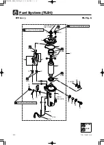
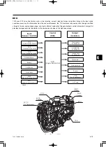
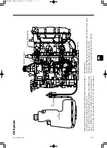
Fuel System (TLDI)

4-4

TLDI  75/90C2  2010

2st

OIL

2st OIL

P/L Fig. 6


 !

"#

$ %& ' $ (%)*+ ,$ -.)%&/

2st OIL

2st

OIL

2st OIL

2st

OIL

2st OIL

2st

OIL

$ %& ' $ (%)*+ ,$ -.)%&/

 %& ' (%)*+ ,$ -.)%&/

TB

1342

1342

2st OIL

2st

OIL

TB

1342

342

1342

1342

FFP Ass'y

MD90C2E̲CH04̲110105.qxd    11.1.5  3:02  PM    ページ 4

Summary of Contents for MD 70-90C2

Page 1: ...OB No 003 21052 2 11 01 NB OB No 003 21052 2 11 01 NB Printed in Japan MD90C2E Cover qxd 11 1 5 10 21 AM 1...

Page 2: ...MD90C2E Cover qxd 11 1 5 10 21 AM 2...

Page 3: ...ledge and skills This manual is utilized so that our customers can always use their outboard motor with full satisfaction Safety Information Safety Statements The following safety statements are found...

Page 4: ...ing it in the hot water of approximately 60 70 C 140 158 F and remove bearing 4 CAUTION Be careful not to burn 5 Donotreuse Lower Unit OIL GEAR GEAR GEAR GRE ASE OBM OBM OBM OBM OIL GEAR GEAR GEAR G17...

Page 5: ...dardized mostly with metric system in the world the metric system includes different kinds of unit systems Though the metric system was established expecting that a single unit system is used in the w...

Page 6: ...I L ADH 1741 1741 O I L GEAR GEAR TB 1373B 1373B 1373B LIT G REASE G17 G17 G17 BO N D 2st O I L TB 1342 1342 LT 518 518 O IL CO M P SOC SOC SOC G REASE MOL MOL MOL TEF G REASE III 0 1 2 34 5 1 5 Moly...

Page 7: ...uel Filter 3 7 4 Inspection of Air Compressor Air Filter 3 7 5 Inspection of Air Pressure 3 7 6 Inspection of Fuel Pressure 3 8 7 Inspection of Drive Belt 3 9 8 Adjustment of Drive Belt Tension 3 9 5...

Page 8: ...ead Cover 5 29 16 Inspection of Cylinder Head 5 30 17 Removing Exhaust Cover 5 31 18 Inspection of Exhaust Cover 5 32 19 Removing Crank Case 5 32 20 Removing Pistons 5 34 21 Disassembly of Crank Shaft...

Page 9: ...ervoir 7 34 19 Disassembly and Assembly of Gear Pump 7 35 20 Disassembly of Tilt Cylinder and Trim Cylinder 7 36 21 Assembly of PTT Unit 7 37 22 Air Bleeding PTT Unit 7 40 8 Electrical System 1 Specia...

Page 10: ...il 10 6 3 Electric Fuel Pump 10 6 4 Installation of Fuel Filter 10 6 5 Connection of Fuel Hose 10 7 6 Filling Fuel System 10 7 7 Filling Oil Tank 10 7 8 Priming Oil Pump 10 8 4 Connections to Outboard...

Page 11: ...8 9 10 11 Service Information Service Data Maintenance Fuel System TLDI Power Unit Lower Unit Cowl Bracket and PTT Unit Electrical System Troubleshooting Rigging Wiring Diagram INDEX OK r min MD90C2E...

Page 12: ...TLDI 75 90C2 2010 x MD90C2E CH00 110105 qxd 11 1 5 11 05 AM 10...

Page 13: ...uments 1 5 3 Special Tools 1 6 4 Pre delivery Inspection 1 9 1 Steering Handle 1 9 2 Gear Shift and Throttle 1 9 3 Engine Oil 1 9 4 Gear Oil 1 9 5 Check quantity of engine oil 1 10 6 Fuel Line 1 11 7...

Page 14: ...park or static electricity 2 Ventilation Exhaust gas or gasoline vapor is hazardous Be sure to ventilate well when working indoors 3 Protection Wear a pair of goggles working gloves and safety shoes t...

Page 15: ...escribed in this manual and use tightening torque specified 6 Recommendations on Service Remove foreign substances and dirt from outboard motor and individual parts by cleaning Apply recommended oil o...

Page 16: ...areful of the fit repair limits air tightness clogging of oil holes for oil feeding or greasing packings wirings pipings and other detailed parts For the components that use many bolts and nuts such a...

Page 17: ...ially available ones Circuit tester Resistance 1 10 10 k AC voltage 30 to 300V DC voltage 30V Internal voltage 3V or less Vernier calipers M1 type 300 mm Micrometer minimum graduation of 0 01 outer 0...

Page 18: ...using Puller Ass y P N 353 72252 0 Removing spring pin Spring Pin Tool A 3 5 P N 369 72217 0 Installing spring pin Spring Pin Tool B 3 5 P N 369 72218 0 Bevel Gear Bearing Puller Ass y P N 3B7 72755 0...

Page 19: ...ar bearing Measuring backlash Backlash Measuring Tool Clamp P N 3B7 72720 0 Used to attach dial gauge when measuring backlash Dial Gauge Plate P N 3B7 72729 0 Measuring backlash between forward A gear...

Page 20: ...oil seal Oil Seal Attachment P N 3T1 99820 0 79 5 x 39 5 Bearing install Tool P N 3T1 99900 0 Attaching drive shaft bearing Attaching air compressor bearing Bearing Attachment P N 3T1 99905 0 51 5 x...

Page 21: ...ion a to check that the throttle operations are smooth 3 Engine Oil Supply engine oil Engine Oil Genuine Oil Oil for two stroke direct injection engine recommended by the outboard manufacturer OIL CAU...

Page 22: ...l level CAUTION When quantity of fills below 1 1L 0 29gal oil warning lamp blinks and the buzzer sounds three times successively every two minutes Oil Tank Capacity 4 3L 1 14 gal Engine Oil Genuine Oi...

Page 23: ...l Use of fuel mixed with engine oil will cause engine trouble 8 Inspection of PTT Unit 1 Operate PTT switch to check that outboard motor tilts up down smoothly 2 Operate PTT switch to check that tilti...

Page 24: ...n of Start Switch and Stop switch 1 Turn main switch to START 2 to check that engine starts 2 Turn main switch to OFF 3 to check that engine stops Switch Panel Model Remote Control Model 3 Press stop...

Page 25: ...idle speed is as specified using key switch depression Idle Speed 700 800 900 r min RPM Tachometer P N 3AC 99010 0 12 Propeller Selection Select a propeller that is best suited to type of boat and ap...

Page 26: ...trim tab 1 as described below and then tighten the nut to specified torque Trim Tab Nut 2 13 N m 9 lb ft 1 3 kgf m 2 Trim Tab Do not reuse Change trim tab angle a little for each test run and repeat t...

Page 27: ...ine read tachometer to check idling engine speeds specified below Complete test run during break in operation Trolling Engine Speeds 700 800 900 r min RPM 4 Run at 3 000 r min or half of WOT for initi...

Page 28: ...1 16 Service Information TLDI 75 90C2 2010 MD90C2E CH01 110105 qxd 11 1 5 10 18 AM 16...

Page 29: ...mp Dimensions 2 3 2 Cooling Water System Diagram 2 4 3 Specifications 2 6 4 Maintenance Data 2 8 5 Torque Specifications 2 14 6 Sealant And Lubricant 2 16 7 Warning Indication List Display for abnorma...

Page 30: ...in 517 20 35 C Transom UL mm in 644 25 35 E mm in 810 31 89 H mm in 623 24 53 I mm in 544 21 42 J mm in 31 70 1 22 2 76 K mm in 598 23 54 Transom L mm in 967 38 07 L Transom UL mm in 1084 42 68 M mm...

Page 31: ...in 125 5 mm 4 94 in 125 5 mm 4 94 in 121 mm 4 76 in 121 mm 4 76 in 13 5 mm 0 53 in 17 5 mm 0 69 in 51 mm 2 01 in 254 mm 9 98 in 353 mm 13 90 in 187 mm 7 36 in M12P1 25 163 5 mm 6 44 in 163 5 mm 6 44 i...

Page 32: ...2 4 Service Data TLDI 75 90C2 2010 2 Cooling Water System Diagram 1 2 3 4 5 6 7 q 8 9 0 w e r MD90C2E CH02 110105 qxd 11 1 5 3 05 PM 4...

Page 33: ...2 5 2 TLDI 75 90C2 2010 1 2 3 4 5 6 7 8 9 0 q r e w MD90C2E CH02 110105 qxd 11 1 5 3 05 PM 5...

Page 34: ...TLDI 75 90C2 2010 3 Specifications 012 3 0 2 3 4 3 5 6 7 3 8 7 9 1 3 4 9 7 7 7 3 0 3 7 2 3 4 5 4 5 7 7 7 4 6 8 7 7 5 A 3 5 4 4 6 4 B 7 4 5 4 6 5 4 5 7 6 7 7 7 3 C D 01 E2 B 4 B MD90C2E CH02 110105 qxd...

Page 35: ...el and Oil 0 1 0 1 2 3 4 056 738 9 9 1 1 Lower Unit 7 1 7 7 7 6 A 3 4 738 B 1 3 3 1 Item Unit Model TLDI75C2 EPT0 TLDI90C2 EPT0 8 Bracket 7 1 7 3 3 C 5 D 7 E 3 C 3 F1 3 6 7 3 D 3 1 1 6 MD90C2E CH02 11...

Page 36: ...2 8 Service Data TLDI 75 90C2 2010 0 0 0 1 0 0 2 0 00 3 2 2 0 45 3 45 2 6 6 7 8 9 0 3 6 3 3 3 3 3 1 0 6 8 7 6 A B C 3 3 0 3 4 Maintenance Data MD90C2E CH02 110105 qxd 11 1 5 3 05 PM 8...

Page 37: ...2 9 2 TLDI 75 90C2 2010 0 0 12 3 4 5 6 7 MD90C2E CH02 110105 qxd 11 1 5 3 05 PM 9...

Page 38: ...0 12 1 A A 0 A B 0 12 1 0 12 1 C D C 0 0 12 1 0 12 1 5 5 0 12 1 8 4 8 E2 6 6 F 0 6 G 7 6 G 7 6 G 0 89 12 1 0 4 CF 6 A 2 H I JK H B K 5 A 5 J B B A L 7 47 7 L A 5 5 L AF M N 5F M 6 I 25 25 H A J A C A...

Page 39: ...ic Whenpartsnolongerconformtostandardvalues Whenpartsnolongerconformtostandardvalues Whenpartsnolongerconformtostandardvalues Whenpartsnolongerconformtostandardvalues Whenpartsnolongerconformtostandar...

Page 40: ...ce Data TLDI 75 90C2 2010 0 1 2 3 0 4 560 6 4 5 1 2 7 4 34 4 1 2 8 1 2 6 3 3 9 5 3 406 06 0 3 5 4 6 5 0 1 34 3 45 0 4 5 3 6 03 6 4 1 6 4 4 6 6 4 A 6 B 4 B C 5B 6 B 3 7 MD90C2E CH02 110105 qxd 11 1 5 3...

Page 41: ...2 13 2 TLDI 75 90C2 2010 MD90C2E CH02 110105 qxd 11 1 5 3 05 PM 13...

Page 42: ...4 Service Data TLDI 75 90C2 2010 2 4 1 3 2 4 1 3 1 3 0 1 1 2 3 4 3 5 66 7 8 9 7 5 66 4 8 9 7 9 7 2 0 2 0 3 0 3 0 6 1 0 1 2 3 4 0 1 2 3 4 5 Torque Specifications MD90C2E CH02 110105 qxd 11 1 5 3 05 PM...

Page 43: ...2 15 2 TLDI 75 90C2 2010 A B MD90C2E CH02 110105 qxd 11 1 5 3 05 PM 15...

Page 44: ...2 16 Service Data TLDI 75 90C2 2010 6 Sealant And Lubricant 0 1 1 1 2 3 0 4 5 6 5 748 7494 7 79 7987 47 5 28 7 MD90C2E CH02 110105 qxd 11 1 5 3 05 PM 16...

Page 45: ...ector Terminal Fuel Injector O Ring Fuel Injector Terminal Fuel Regulator O Ring Air Regulator O Ring Compression Seal Plug O Ring Air Hose L Nipple O Ring Fuel Hose L Nipple O Ring Valve Ass y Piston...

Page 46: ...ervice Data TLDI 75 90C2 2010 01 1 2 2 3 4 2 2 2 25 2 2 2 2 6 2 2 2 2 25 2 2 2 78 6 992 9 25 25 2 2 2 2 6 2 2 254 2 25 25 2 25 5 2 6 0 5 2 2 3 3 3 0 1 1 1 0 90 99 A MD90C2E CH02 110105 qxd 11 1 5 3 05...

Page 47: ...2 19 2 TLDI 75 90C2 2010 0 1 2 3 4 3 5 6 078 2 2 7 7 9 2 9 1 9 5 MD90C2E CH02 110105 qxd 11 1 5 3 05 PM 19...

Page 48: ...2 20 Service Data TLDI 75 90C2 2010 7 Warning Indication List Display for abnormalities during operation MD90C2E CH02 110105 qxd 11 1 5 3 05 PM 20...

Page 49: ...2 21 2 TLDI 75 90C2 2010 000 1 234 234 504 5 4 504 5 4 004 4 56 06 26 06 7 1 7 8 7 7 9 9 7 000 9 7 000 7 8 MD90C2E CH02 110105 qxd 11 1 5 3 05 PM 21...

Page 50: ...2 22 Service Data TLDI 75 90C2 2010 MD90C2E CH02 110105 qxd 11 1 5 3 05 PM 22...

Page 51: ...of Spark Plugs 3 10 2 Inspection of Compression Pressure 3 11 3 Inspection of Thermostat 3 12 4 Inspection of Cooling Water Passage 3 13 6 Operating System 3 13 1 Adjustment of Throttle Cable 3 13 2...

Page 52: ...talling spring pin Spring Pin Tool B 3 5 P N 369 72218 0 Measuring air rail fuel pressure and air pressure Pressure Gauge Ass y P N 3T5 72880 0 Compression Gauge P N 3AC 99030 0 Measuring compression...

Page 53: ...etighten Greasing Grease Nipple grease Anode Deterioration corrosion Note It is recommended to perform complete inspection every 300 hours of operation 2 Inspection Schedule Fuel System and Compressio...

Page 54: ...nk 3 Disconnect oil filter inlet hose and then reconnect the hose when oil containing no air bubbles flows out 2 Oil Filter and Oil Tank 1 Only clean if debris water or contamination is present If cle...

Page 55: ...eed oil When air is bled from the oil set the key switch to OFF 4 Pull twice Beep Beep Beep Beeps three times 6 Pull stop switch 4 twice within two seconds When the above operation is completed the bu...

Page 56: ...k dirt deterioration and damage and replace or clean parts if necessary 2 Inspection of Fuel Tank option Turn fuel pick up elbow 2 of fuel tank 1 counterclockwise to remove the part and clean the filt...

Page 57: ...Specified Value 0 61 0 70 MPa 88 47 101 53 psi 6 1 7 0 kgf cm2 The air pressure reduces gradually after stopping the engine or cranking 4 O Ring Do not reuse CAUTION Continuing engine operation with...

Page 58: ...aching pressure gauge ass y cover the joint of inspection valve and gauge with rag to prevent spread of fuel that leaks Screw in the pressure gauge carefully until it is set securely Pressure Gauge As...

Page 59: ...Belt in Chapter 4 8 Adjustment of Drive Belt Tension 1 Loosen compressor securing bolts 2 While pushing compressor toward cylinder head a tighten the securing bolts to fix the compressor 155 7 m m 6...

Page 60: ...park Plug 25 N m 18 lb ft 2 5 kgf m a 2 1 2 2 Clean spark plug electrodes 1 by using spark plug cleaner Replace if necessary 3 Check electrodes 1 for corrosion or excessive build up of carbon and wash...

Page 61: ...gine oil into cylinders and perform the test again If compression pressure increases after the above measure check pistons and piston rings for wear Replace if necessary If compression pressure does n...

Page 62: ...ied value Water Temperature Valve Lift a 75 C 167 F 4 5 mm 0 177 in or more 3 Hang thermostat 3 in the water contained in vessel 4 Put thermometer in the water and warm up water to measure valve openi...

Page 63: ...emove R shaped pin 2 and washer 3 3 Remove cable joint 4 from advancer arm 5 4 Bring advancer arm 5 to full close stopper 6 5 Set remote control lever to neutral N position 7 6 Adjust cable joint scre...

Page 64: ...can be made smoothly If necessary readjust by following the steps 1 to 7 F R N R F N N R F 7 Attach cable joint washer and R shaped pin to advancer arm 8 Check if throttle control can be made smoothly...

Page 65: ...heck PTT fluid quantity if necessary Refer to Inspection of PTT Fluid Quantity 1 Check that PTT motor produces noise of normal revolution 2 Inspection of PTT Fluid Quantity 1 Fully tilt up outboard mo...

Page 66: ...case 2 1 4 Attach upper oil plug 1 and new gasket 2 2 2 Remove cap 2 and check PTT fluid quantity CAUTION Be sure to remove the cap when outboard motor is in full tilt up position Removal of the cap...

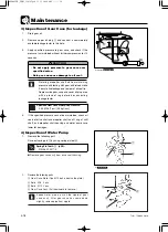
Page 67: ...d lower oil plug 1 quickly Gear Oil Tohatsu genuine Gear Oil or Hypoid Gear Oil API GL 5 SAE 80 90 Gear Oil Quantity 900 cm3 30 4 fl oz OIL 2 1 a 2 1 2 1 3 a 3 3 Check gear oil for presence of metal p...

Page 68: ...pin 1 by using spring pin tool 2 Spring Pin Tool A 2 3 0 P N 369 72217 0 Remove gear case ass y from drive shaft housing 2 Remove the following parts 3 Gear Case Plate One M10 bolt is behind the plate...

Page 69: ...entation 1 9 Others 1 Replacement of Anode 1 Dirt on Anode and Trim Tab Check if grease or oil is adhered to the components Clean if necessary Anodes are used in the exhaust cover cylinder body clamp...

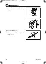
Page 70: ...eterioration Replace anode or trim tab if volume is reduced to 2 3 of new part 2 Inspection of Propeller 1 Check propeller blades and hub for cracks damages wear and corrosion Check spline for twist a...

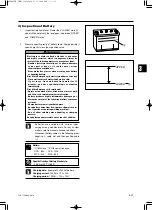
Page 71: ...ith fresh water if adhered to skin If gets in eye flush well with fresh water for 15 minutes and have ophthalmologic evaluation immediately First Aid in Emergency if swallowed Gargle using much water...

Page 72: ...and stop water supply remove 3 attach and tighten 1 and then reinstall propeller parts removed Flushing using drive cleaner P N353 72406 0 1 Put drive cleaner 1 on the gear case from the front so tha...

Page 73: ...er for 3 to 5 minutes CAUTION The flushing can be made without running the engine Water pressure 0 12 0 2MPa 1 74 29 0psi 1 2 2 0kgf cm2 4 Remove flushing attachment 5 Check if seal rubber 3 and O rin...

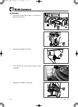
Page 74: ...E OBM OBM OBM OBM LIT G REASE LIT 5 Greasing 1 Inject grease through grease nipple 1 until excessive grease appears from a 2 Apply grease to propeller shaft spline 3 Only under pinion on splines outsi...

Page 75: ...26 4 Removing Vapor Separator 4 26 5 Disassembly and Inspection of Vapor Separator 4 27 6 Assembly of Vapor Separator 4 27 7 Assembly of Vapor Separator Ass y 4 28 8 Removing FFP Ass y 4 28 9 Disasse...

Page 76: ...ent P N 3T1 99905 0 51 5 x 39 5 Used to press fit crank case head oil seal Oil Seal Attachment P N 3T1 99820 0 Piston Slider P N 3T1 72871 0 3T1 72871 0 Assembling piston for air compressor Caulking c...

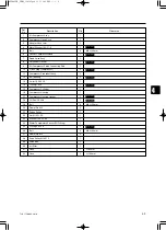
Page 77: ...21 Gasket B Diaphragm 1 22 Check Valve 2 23 Screw 2 M3 L 6mm 24 Nut 2 M3 25 Diaphragm Set 1 26 Gasket Fuel Pump 1 Ref No Description Remarks Q ty 2st O I L 2st OIL P L Fig 8 27 Bolt 2 M6 L 40mm 28 Wa...

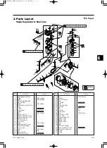
Page 78: ...TLDI 4 4 TLDI 75 90C2 2010 2st O I L 2st OIL P L Fig 6 2st OIL 2st O I L 2st OIL 2st O I L 2st OIL 2st O I L TB 1342 1342 2st OIL 2st O I L TB 1342 342 1342 1342 FFP Ass y MD90C2E CH04 110105 qxd 11 1...

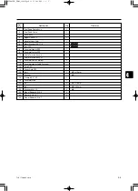
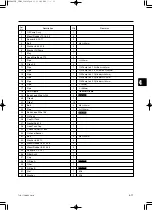
Page 79: ...11 Cable Terminal Ass y 1 12 Grommet Cable Terminal 2 13 Grommet Upper Cable Terminal 1 14 Cord FFP 1 15 Cover Cord FFP 1 16 Bolt 1 M5 L 12mm 17 Washer 1 M5 18 Clamp 6 5 47 5P 1 19 Grommet Pipe 1 20 B...

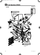
Page 80: ...GM GM SOC SOC SOC 2st OIL 2st O I L 2st OIL 2st O I L S O C O IL CO M P GM GM SOC SOC SOC 2st OIL 2st O I L 2st OIL 2st O I L TB 1342 1342 P L Fig 4 2st O I L 2st OIL TB 1342 342 1342 1342 O IL CO M P...

Page 81: ...1 25 Regulator Air 1 650Kpa 26 O Ring 2 5 20 1 27 O Ring 5 2 5 1 28 Plate Fuel Injector 2 29 Holding Plate 1 30 Lead Wire Band 170 2 31 Lead Wire Band Stay 2 32 Air Hose Ass y 1 33 O Ring 1 9 9 8 2 3...

Page 82: ...2st OIL 2st O I L 2st OIL 2st O I L 2st OIL 2st O I L TB 1342 1342 S O C O IL CO M P GM GM SOC SOC SOC OBM G REASE OBM OBM OBM OBM P L Fig 5 2st O I L 2st OIL TB 1342 342 1342 1342 LIT G REASE LIT G R...

Page 83: ...mpressor Cylinder 1 16 Compressor Housing 1 17 Compressor Housing Gasket 1 18 Oil Seal 25 45 8 1 19 Bolt 4 M6 L 25mm 20 Dowel Pin 4 10 2 21 Driven Pulley 1 22 Nut M10P1 25 1 23 Washer 10 5 20 3 2 1 24...

Page 84: ...Fuel System TLDI 4 10 TLDI 75 90C2 2010 Oil Pump P L Fig 13 MD90C2E CH04 110105 qxd 11 1 5 3 02 PM 10...

Page 85: ...L 40mm 17 Pipe 1 L 465mm 18 Joint Nipple 1 Reducer Nipple 19 Band Lead Wire L 104 2 20 Clip 8 1 21 Clip 7 13 22 Bolt 2 M6 L 30mm 23 Pipe 1 L 1150mm 24 Band Lead Wire 158 1 25 Oil Tank 1 26 Cap Oil Tan...

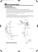
Page 86: ...consumption and lower emission as well as powerful performance that is one of outstanding features of two stroke engines 2 Air assisted low pressure direct fuel injection The air assisted low pressure...

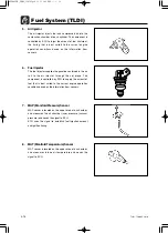
Page 87: ...function together to detect openings of intake valve throttle butterfly and throttle advancer arm of the throttle body and transmits the signals to ECU 2 CPS Crank Position Sensor CPS detects the cran...

Page 88: ...or through the set piece The component is controlled by ECU to supply the amount of fuel that is best suited to the current engine operation conditions based on the information from sensors 7 MAP Mani...

Page 89: ...s based on the information from the sensors Moreover the TLDI achieves lean combustion through stratified charge in the low engine speed range and highly efficient combustion through electronic contro...

Page 90: ...ough FFP case 9 The returned gasoline contains small amount of air bubbles that are produced when the gasoline was compressed with 5 The air bubbles are sent to the throttle body 0 from upper part of...

Page 91: ...s split into the ports of the following nine components here cylinder 1 crank case 4 cylinder 2 crank case 5 cylinder 3 crank case 6 air compressor 7 air box 1 8 air box 2 9and air box 3 0 For 4 5 6 a...

Page 92: ...air box flows to interior of crank case e of cylinder 2 to lubricate it Then the oil that is deposited in the scavenging passage of each cylinder flows from 1 cylinder scavenging passage r to 3 cylind...

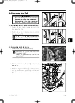
Page 93: ...y 1 Remove stopper plate 1 and pull out hose 2 2 Remove compressor side hose joint 3 and remove air hose ass y 3 3 Remove cooling water outlet hose 7 and then fuel return hose 6 air exhaust hose 5 an...

Page 94: ...o loosen O ring and insert bladed screw drivers from both sides to remove it up straight evenly Be careful not to drop O ring located on the air injectors Pull the air rail straight without applying f...

Page 95: ...mbling Diagram in page 4 23 2 3 e w q 8 9 0 7 9 0 r 4 6 5 2st OIL 2st O I L 2st OIL 2st O I L 2 3 1 2st OIL 2st O I L a 2st O I L 2st OIL O Ring Set Tool 24 P N 3T5 72863 0 CAUTION To avoid incorrect...

Page 96: ...orientation shown by arrow A Check that injectors are free from waste textile and other dirt before installing Correct Wrong Face passage opening toward you View from Arrow A 5 Attach fuel injector a...

Page 97: ...using collars 4 plate 5 and bolt 6 and attach clamp 7 Be sure to install collar 4 below plate 5 Attach hose to fuel regulator by using hose clamp 2 Do not reuse hose clamp Always use new one 2 Removin...

Page 98: ...y to cylinder head and secure with bolts Set air injector with coupler side directing to port side of engine Check that injectors are free from waste textile and other dirt before installing Install...

Page 99: ...llowing parts 1 Remove fuel hose ass y 1 after loosening joint between FFP 5 and air rail 6 Use rag to catch fuel that spills from the parts 5 and 6 when they are removed 2 Remove high pressure fuel f...

Page 100: ...hen drain screw 2 1 4 6 5 2 7 3 6 2 5 6 4 1 Use rag to catch fuel that spills from the part 2 when it is loosened 2 Pull out following hoses Vapor Exhaust Hose 3 Vapor Separator Throttle Body Vapor Re...

Page 101: ...the vapor separator Replace if necessary 6 Assembly of Vapor Separator 1 Assemble following parts 1 Float Valve 2 Float 3 Float Arm Pin 4 Tighten screw Screw 4 1 6 N m 1 1 lb ft 0 16 kgf m 5 Drain Sc...

Page 102: ...eturn Hose 4 FFP Vapor Separator Fuel Hose 5 Vapor Separator FFP 3 Loosen two bolts 6 and remove FFP Use rag to catch fuel that spills from each hose when it is disconnected 9 Disassembly and Inspecti...

Page 103: ...il 2st O I L 3 Install FFP 6 to case 7 Adjust position of FFP body so that pipe grommet 4 can be inserted into upper case 3 Lightly applying 2 stroke engine oil on inside and outside of upper grommet...

Page 104: ...3 lb ft 0 32 kgf m 6 Attach cable terminal grommet upper u put seal ring O ring i and upper case 3 and then secure the parts with bolts o Cable Terminal Grommet Upper u O Ring i Genuine Engine Oil 2st...

Page 105: ...b ft 1 5 kgf m Connect FFP cord connector cord ass y 7 and secure it with clamp 8 4 Apply specified vacuum pressure to check that no air leaks through check valve located in the fuel pump 6 Apply spec...

Page 106: ...or If performing the work after stopping the engine do it after cooling the high pressure hose because it is made hot during the operation 3 6 2 5 4 3 4 6 1 2 3 6 5 4 2 Loosen compressor mounting bolt...

Page 107: ...e the belt with new one if any of the above problems exists Crack or chip of the belt if any can be found easily when it is turned over 4 Removing Driven Pulley 1 Remove compressor cylinder 1 from air...

Page 108: ...l 1 and bearing 2 1 2 2 CAUTION Be careful not to damage the crank pin 1 area when fixing crank shaft using a vice Heat compressor housing to 60 to 70 degrees Centigrade 140 to 158 degrees Fahrenheit...

Page 109: ...pply two stroke engine oil to periphery of bearing 3 and install it into compressor housing by using a press 2st OIL 2st O I L 3 1 2 Driver Rod 1 P N 3AC 99702 0 Bearing Attachment 2 P N 3T1 99905 0 2...

Page 110: ...eal when it is installed 9 Installation of Crank Shaft 1 Install crank shaft 1 to the housing 2 and fix the crank shaft at its lower end by using a vice 2 Attach collar 3 O ring 4 and driven pulley 5...

Page 111: ...two stroke engine oil to cylinder inner wall 3 piston periphery and piston rings and install piston ass y to the cylinder so that UP mark of the piston head is at the pulley side 2st O I L 2st OIL CAU...

Page 112: ...b ft 0 6kgf m Put crank pin into connecting rod big end and install the assembly while shaking crank shaft a little Cylinder Head Bolt 8 9N m 7 lb ft 0 9kgf m 3 Install head 5 reed valve ass y 6 and g...

Page 113: ...ent of Fuel Pressure and Air Pressure 1 Use pressure gauge ass y to measure fuel pressure and air pressure in the air rail Pressure Gauge Ass y P N 3T5 72880 0 Perform the measurements by using the me...

Page 114: ...URE Typical Value 0 65 MPa 94 3 psi 6 5 kgf cm2 0 72 MPa 104 4 psi 7 2 kgf cm2 Specified Range of Pressure 0 61 0 58 MPa 88 47 101 53 psi 6 1 7 0 kgf cm2 Air Pressure 0 06 0 08 MPa 8 70 11 60 psi 0 6...

Page 115: ...filter is cracked damaged or leaks or if dirt or water is in it Clean or replace if necessary 14 Inspection of Oil Tank Check if oil tank is cracked damaged or leaks or if dirt or water is in it Clean...

Page 116: ...et line black on filter ON OFF START 1 2 3 Beep 4 Set key switch 1 to ON 5 Pull off lock plate 3 within one second from the moment warning buzzer 2 stops 7 The oil pump continues to operate to feed oi...

Page 117: ...Inspection of Exhaust Cover 5 32 19 Removing Crank Case 5 32 20 Removing Pistons 5 34 21 Disassembly of Crank Shaft 5 35 22 Inspection of Crank Shaft 5 35 23 Inspection of Cylinder 5 36 24 Inspection...

Page 118: ...r bearing Universal Puller Plate P N 3AC 99750 0 Used to press fit coil bracket oil seal Oil Seal Attachment P N 3U1 99820 0 51 5 x 39 5 Used to press fit crank case head oil seal Oil Seal Attachment...

Page 119: ...ing Gear Cover Ass y 1 3 Gasket 1 4 Dowel Pin 2 5 Bolt 8 L 107mm x 6 L 120mm x 2 6 Apron 1 7 Screw 4 M6 L 12mm W PW 8 Battery Cord 1 9 Screw 2 M6 L 16mm W PW Ref No Description Remarks Q ty Ref No Des...

Page 120: ...5 4 Power Unit TLDI 75 90C2 2010 P L Fig 9 Magneto MD90C2E CH05 110105 qxd 11 1 5 10 07 AM 4...

Page 121: ...lywheel W Gear 1 2 Alternator Ass y 1 3 Bolt 7 M6 L 30mm 4 Coil Bracket 1 5 Dowel Pin 6 12 2 6 Crank Position Sensor 1 7 Bolt 2 M5 L 12mm 8 Key Magneto 1 Ref No Description Remarks Q ty MD90C2E CH05 1...

Page 122: ...43 43 20 21 19 26 26 25 24 25 35 31 28 42 36 23 22 N m 16 lb ft 2 2 kgf m SOC O IL CO M P GM SOC SOC SOC O IL CO M P GM SOC SOC SOC O IL CO M P GM SOC SOC SOC O IL CO M P GM SOC SOC 6 N m 4 lb ft 0 6...

Page 123: ...L 12mm 24 Lead Wire Band 170 5 25 Stay 4 26 Bolt 3 M6 L 12mm 27 Band Lead Wire 158 2 28 Electric Bracket 1 29 Bolt 3 M6 L 25mm 30 Washer 6 16 1 5 3 31 Mount Rubber 8 5 12 2 6 32 Spacer 6 2 9 10 7 3 3...

Page 124: ...2 10 Spacer 8 4 12 21 5 2 11 Mount Rubber A Starter 2 Ref No Description Remarks Q ty 12 Starter Motor Mount 1 13 Starter Motor Bracket Upper 1 14 Bolt 2 M8 L 45mm 15 Washer 2 M8 16 Starter Motor Brac...

Page 125: ...asket Inlet Manifold 1 5 Bolt M6 35 12 M6 L 35mm 6 Air Chamber Cover 1 7 Air Chamber Cover Gasket 1 8 Dowel Pin 4 10 2 9 Bolt 9 M8 L 45mm 10 Grommet 1 11 Reed Valve Ass y 3 Ref No Description Remarks...

Page 126: ...LIT G REASE LIT TB 1342 1342 LIT G REASE LIT LIT G REASE LIT TB 1342 1342 OBM G REASE OBM OBM OBM TB 1342 1342 1342 P L Fig 7 Throttle TB 1342 1342 1342 LIT G REASE LIT G REASE OBM OBM OBM MD90C2E CH...

Page 127: ...ark 3T9 13 2 Throttle Body Ass y 1 75ps Mark 3FY 14 Throttle Cam 1 15 Bolt 1 M6 L 16mm 16 Washer 6 5 21 1 1 17 Bushing 6 24 7 1 18 Ball Joint B 1 19 Nut 1 M6 20 Washer 1 M6 21 TPS Ass y 1 22 Mount Rub...

Page 128: ...2 2010 1 2 3 4 1 2 3 4 2st O I L 2st OIL 518 L T 518 LIT G REASE LIT 2st O I L 2st OIL 2st O I L 2st OIL LIT G REASE LIT P L Fig 1 2st O I L 2st OIL 518 518 L T 518 Cylinder Crank Case MD90C2E CH05 11...

Page 129: ...y 1 29 Gasket Exhaust Cover 1 30 Bolt 16 M6 L 25mm 31 Anode 1 32 Bolt 1 M6 L 16mm 33 Anode Plug 1 34 Seal Ring 1 35 Bolt 1 M6 L 20mm 36 Anode 1 37 Bolt 1 M6 L 30mm 38 Crankcase Head 1 39 O Ring 2 74 5...

Page 130: ...d 35 7 Main Bearing Upper 1 8 Oil Seal 36 46 6 1 9 O Ring 2 4 44 7 1 10 Washer 66 85 2 1 11 1 Piston STD 3 STD 11 2 Piston 0 5 O S 3 OPT 0 5O S 12 1 Piston Ring 1st STD 9 STD 1st 2nd 3rd 12 2 Piston R...

Page 131: ...or varies much among cylinders put small amount of engine oil into cylinders and perform the test again If compression pressure increases after the above measure check pistons and piston rings for wea...

Page 132: ...e ring gear cover 3 3 Remove PTT cable 3 from solenoid switch 4 4 4 Disconnect connector 4 of PTT switch Disconnect battery cables from battery terminal 1 1 2 2 2 Disconnect battery cables 1 from star...

Page 133: ...emove R shaped pins and then throttle cable 7 and shift cable 8 9 8 Remove shift assist ass y 9 from shift arm Be careful not to lose washers that are removed together with cables 0 0 9 Loosen clip of...

Page 134: ...the port side of bottom cowl w w 11 Disconnect fuel hose w from fuel filter e 12 Remove apron e 13 Loosen outside engine mount bolts first and then remove all of them WARNING Disconnect hose while hol...

Page 135: ...oist power unit taking care not to catch wires and hoses Eye Bolt r P N 3T1 72212 0 3 Removing Air Compressor Refer to Removing Air Compressor in chapter 4 Put the tip of bladed screw driver in the ma...

Page 136: ...hand Turn center bolt clockwise to remove flywheel Removing breather hose of vapor separator makes the work easier Flywheel Puller Lit P N 3T1 72211 0 5 Removing Alternator 1 Remove oil tank installat...

Page 137: ...ve alternator 5 Loosen coil bracket securing bolts M6 4 pieces and remove bracket 6 Removing Starter Motor 1 Remove starter motor securing band and securing bolts M8 2 pcs on the upper surface and the...

Page 138: ...water temperature sensor connector while pushing hook of the connector 4 Disconnect fuel injector connector while pushing hook of the connector Repeat this step for three cylinders 5 22 Power Unit TL...

Page 139: ...of the connector 9 Disconnect MAP and MAT sensor connector while pushing hook of the connector option 8 Disconnect TPS connectors while pushing hook of the connector Connector on the outer Blue T2 Con...

Page 140: ...ing wire of cord ass y is secured together 11 Disconnect overheat sensor connector located on the cylinder block while pushing lock of the connector 13 Disconnect cord ass y from terminal Remove ignit...

Page 141: ...2 pcs and then remove pump together with pump bracket Disconnect oil hose from crank case Refer to Oil System in Chapter 4 Use waste cloth to let it soak with oil if spilt from hose 1 3 2 9 Removing...

Page 142: ...5 Washer 8 5 24 1 5 6 Washer 12 5 24 1 7 Collar 8 Bushing 9 Throttle Link Rod Snap 0 Rod Snap Check link rod snap for wear and damage 1 7 85 3 0 2 6 5 4 9 10 Inspection of Throttle Body 1 Check thrott...

Page 143: ...ion hose Refer to Recirculation System in Chapter 4 When air chamber cover is removed the oil collected in the cover may flow out Use rag to catch the oil 2 Loosen throttle body mounting bolt and remo...

Page 144: ...out of the specified range a Reed Valve Stopper Height b 9 2 9 4 mm 0 362 0 370 in Reed Valve Bend a Replace reed valve with new one if its bend is over the limit 12 Removing Thermostat 1 Loosen ther...

Page 145: ...open even a little at ambient temperature 3 a 2 Measure valve lift of thermostat when prescribed temperature has been reached Replace if the length is less than specified value 15 Removing Cylinder H...

Page 146: ...original size 16 Inspection of Cylinder Head 1 Remove carbon deposit in the combustion chamber of cylinder head and check the interior for degradation damage and other defects 2 Check water jacket int...

Page 147: ...nd moving it on the paper drawing the letter 8 on it Finish by using sand paper 600 17 Removing Exhaust Cover 1 Loosen exhaust cover mounting bolts in the order shown remove them and remove exhaust co...

Page 148: ...cover Replace if 2 3 of the original size 19 Removing Crank Case 1 Remove starter motor bracket 2 Loosen crank case mounting bolts in the order shown remove them and remove crank case Pry the gap of t...

Page 149: ...11 7 4 8 12 9 5 1 13 3 3 Remove crank shaft ass y Put a pipe of 19mm 0 748 in in the drive shaft side of crank shaft ass y hold the crank shaft ass y using both hands lift it in parallel with the cyli...

Page 150: ...ve piston pin 1 washer and needle bearing 3 Remove piston rings Use piston ring remover Piston Ring Tool P N 353 72249 0 Use piston pin tool 2 if necessary Put the piston pin tool on the piston pin an...

Page 151: ...ified value 1 2 3 21 Disassembly of Crank Shaft 1 Remove main bearing Lower Remove C ring 1 and pull out spacer 2 Remove main bearing lower 3 by using universal puller plate and universal puller Unive...

Page 152: ...ndard Value 86 00 86 02 mm 3 3858 3 3866 in Oversize Piston 86 5 mm 3 4055 in Functional Limit 86 08 mm 3 3890 in a 10mm 0 39 in b 30mm 1 18 in c 80mm 3 15 in d Crank Shaft Direction e Crank Web Direc...

Page 153: ...nal Limit of taper 0 08 mm 0 0032 in 3 Calculate out of roundness of inner diameter of the cylinder Replace the cylinder or use oversized piston if the out of roundness is equal to or over the specifi...

Page 154: ...piston ring to piston and measure piston ring side clearance Replace piston ring if the clearance is over specified value Piston Ring Tool P N 353 72249 0 Piston Ring End Gap Standard Value Top Ring S...

Page 155: ...ter is over the limit Piston Pin Hole Standard Value 23 00 mm 0 9056 in Functional Limit 23 03 mm 0 9067 in Piston Pin Outer Diameter Standard Value 23 00 mm 0 9056 in Functional Limit 22 97 mm 0 9045...

Page 156: ...35 48 6 16 4 and attach C ring 7 2 3 7 1 2st O I L 2st OIL 4 6 2st O I L 2st OIL Spacer Press Fitting Tool 6 Inner Diameter 36 mm 1 417 in Attach spacer 40 52 7 1 and washer 66 85 2 2 and then press f...

Page 157: ...on pin 72 a 2st O I L 2st OIL G REASE MOL MOL MOL 2st O I L 2st OIL Attach a piston pin clip to a groove in the piston pin hole Assemble the parts so that the side marked with UP on the piston head fa...

Page 158: ...washers 7 in the cylinder grooves snugly 7 7 6 6 4 Bring seal ring gap a to crank case side center a Before assembling parts remove residual gasket on the surface of bearings and mating surfaces of c...

Page 159: ...518 L T 518 Bring knock hole of each bearing to dowel pin of cylinder s journal areas Attempt to move each bearing lightly to check if dowel pin is in the hole snugly Each bearing is provided with a b...

Page 160: ...temporary tightening bolts M8 Tighten crank case securing bolts and nuts in two steps to their specified torque Wipe off excess Loctite 518 from mating surface Rotate Crankshaft to ensure it is not b...

Page 161: ...ch exhaust cover securing bolts to M6 and tighten them in the order of their numbers shown to specified torque 16 1 5 10 14 1 15 11 6 7 8 12 2 16 13 9 3 4 Exhaust cover Bolts 6 N m 4 lb ft 0 6 kgf m T...

Page 162: ...ylinder head securing bolts M8 to in the order of the numbers shown 14 1 4 Finally tighten cylinder head cover securing bolts M6 5 Attach air injectors and air rail to cylinder head Refer to Assembly...

Page 163: ...T G REASE LIT LIT G REASE LIT 1 3 4 2 Apply grease and oil to oil seal 35 589 and press fit it to crank case head 6 Install thermostat thermo cap and gasket 2st O I L 2st OIL LIT G REASE LIT Thermosta...

Page 164: ...shown 12 1 TB 1342 1342 1342 1 1 1 2 Install throttle body then tighten bolts M6 to specified torque TB 1342 1342 1342 When reusing bolts apply screw lock 1342 1 Gasket TB 1342 1342 1342 TB 1342 1342...

Page 165: ...ply ThreeBond 1342 to throttle body securing bolts 3 Attach air chamber cover and gasket Attach and tighten air chamber securing bolts M6 to to specified torque in the order of the numbers shown 9 1 L...

Page 166: ...Valve 2 2 Cylinder Scavenging Passage 185 mm 7 3 in 1 Cylinder Liner Line Check Valve 185 mm 7 3 in 3 Cylinder Liner 3 1 Cylinder Scavenging Passage 4 1 3 2 Inserting Position 20 mm 0 8 in 34 Installa...

Page 167: ...ng procedure described in Removing Cord Ass y in Chapter 5 37 Installation of Fuel System Refer to Removing and Installation of Fuel System in Chapter 4 39 Installation of Starter Motor 1 Secure start...

Page 168: ...side crank case side of engine 41 Installation of Drive Pulley and Flywheel 1 Attach key flywheel and drive pulley to crank shaft and tighten the nut to specified torque Degrease tapered areas of cran...

Page 169: ...curely and tighten engine mount bolts 2 specified torque 5 Install other parts reverse of their removing steps Refer to Electrical Wiring Assembling Instruction Diagrams 1 and 2 in Chapter 11 Engine M...

Page 170: ...5 54 Power Unit TLDI 75 90C2 2010 MD90C2E CH05 110105 qxd 11 1 5 10 08 AM 54...

Page 171: ...er Shaft Ass y 6 21 18 Removing Forward A Gear Ass y 6 22 19 Disassembly of Forward Gear A Gear 6 23 20 Inspection of Forward A Gear 6 23 21 Assembly of Forward A Gear Parts 6 24 22 Removing Drive Sha...

Page 172: ...ing Gauge P N 3B7 72250 0 Driver Rod P N 3AC 99702 0 Used in combination with center place and various attachments Removing reverse C gear bearing Universal Puller Plate P N 3AC 99750 0 Removing prope...

Page 173: ...d in combination with driver rod and center plate Attaching propeller shaft housing needle bearing 31 5 x 25 x H32 79 5 x 39 5 Bearing install Tool P N 3T1 99900 0 Attaching drive shaft bearing Used i...

Page 174: ...EASE OBM OBM OBM OBM TB 1342 1342 TB 1342 1342 G REASE OBM OBM OBM OBM O I L GEAR GEAR GEAR G REASE OBM OBM OBM OBM G REASE OBM OBM OBM OBM G REASE OBM OBM OBM OBM G REASE OBM OBM OBM OBM O I L GEAR G...

Page 175: ...p 1 32 Gasket Pump Guide Plate 1 33 Bolt 4 M8 L 85mm 34 Washer 4 M8 35 Water Strainer Set 1 36 Screw 1 M4 L 45mm 37 Nylon Nut 1 M4 38 Clutch Cam 1 39 1 Cam Rod L 1 for Transom L 7 39 2 Cam Rod UL 1 fo...

Page 176: ...OBM OBM O I L GEAR GEAR GEAR G REASE OBM OBM OBM OBM TB 1342 1342 O I L GEAR GEAR GEAR O I L GEAR GEAR GEAR G REASE OBM OBM OBM OBM G REASE OBM OBM OBM OBM O I L GEAR GEAR GEAR G REASE OBM OBM OBM OBM...

Page 177: ...1 21 Clutch 1 22 Clutch Pin 1 23 Snap Clutch Pin 1 24 Spring Holder Clutch 1 25 Spring Clutch 1 26 Push Rod Clutch 1 27 Ball 3 28 Nut Propeller M16P1 5 1 M16 29 Washer 17 32 3 1 30 Split Pin 1 31 1 P...

Page 178: ...er 6 5 4 3 2 1 Drain all gear oil and check if any metal particle is found in the drained oil Check gear oil color White or cream color possibly indicates that water is contained in the gear oil Note...

Page 179: ...from outboard motor tilting the outboard motor makes the work easier Disconnect shift rod at upper side of shift rod joint 1 Use spring pin tool A 2 to remove spring pin Do not reuse removed spring p...

Page 180: ...ng 1 2 1 3 O I L GEAR GEAR GEAR G REASE OBM OBM OBM OBM 5 Inspection of Clutch Cam 1 Check the part for wear and damage Replace if necessary a b O I L GEAR GEAR GEAR GEAR G REASE OBM OBM OBM OBM Sprin...

Page 181: ...rod 4 7 Removing Water Pump 1 Loosen and remove pump case upper bolts and remove pump case upper parts 1 2 3 and 4 in this order 1 1 2 3 4 6 7 7 Spring Pin Do not reuse Spring Pin Tool B 8 3 5 P N 36...

Page 182: ...and wear Replace if necessary When removing pump case lower insert bladed screw driver into the groove of the case and pry slowly to separate the part The impeller may show gloss or have melted area i...

Page 183: ...and crack on the lip area Replace if necessary 9 Disassembly of Water Pump Case Lower 1 Use bladed screw driver or seal remover to remove oil seal 1 1 Two oil seals are used Note that there is a shim...

Page 184: ...n press fit 4 3 4 1 3 1 1 1 2 1 2 Lip Circumference G REASE OBM OBM OBM OBM O I L GEAR GEAR GEAR O I L GEAR GEAR GEAR GEAR G REASE OBM OBM OBM OBM Oil Seal Attachment 3 P N 3J6 99820 0 Driver Rod 4 P...

Page 185: ...the position where O ring of the housing can be removed 2 3 3 Hold propeller shaft and remove propeller shaft housing ass y When pulling out propeller shaft housing ass y remove clutch push rod and s...

Page 186: ...ove reverse C gear by using bladed screw drivers 3 1 2 3 5 4 Remove bearing 5 CAUTION Heat propeller shaft housing by putting it in the hot water of approximately 60 70 C 140 158 F and remove bearing...

Page 187: ...to remove oil seal 4 and needle bearing 6 at the same time Before removing check bearing for play or deflection Replace if necessary Direct the side of attachment without O ring to needle bearing 6 Wh...

Page 188: ...tment Install needle bearing with the manufacturer s mark a facing the tool side Screw in needle bearing attachment 2 lightly by a hand so that no gap is made at driver rod 1 Clean needle bearing inst...

Page 189: ...o propeller shaft housing Clean bearing installation face and apply gear oil before installation O I L GEAR GEAR GEAR GEAR O I L GEAR GEAR GEAR GEAR Bearing Attachment 8 P N 3U1 99905 0 Driver Rod 1 P...

Page 190: ...to the figure 4 After taking out clutch spring retainer 5 and clutch spring 6 remove clutch 7 from propeller shaft 3 Clutch Pin Snap Do not reuse 3 Clutch Pin Snap Do not reuse WARNING When removing c...

Page 191: ...tch pin 4 to propeller shaft When attaching clutch face the narrower claw a to push rod side When installing spring retainer direct the end farther away from the hole toward forward gear a Install clu...

Page 192: ...e gear case CAUTION Do not reuse removed clutch pin snap When attaching clutch pin snap do not apply excessive force to the part or the snap may expand during operation of the engine resulting in dama...

Page 193: ...ward gear A gear Put the drivers into grooves of forward A gear and pry out taking care not to damage the shim CAUTION Be careful not to damage shim 3 2 Remove needle bearing 4 Drive out needle bearin...

Page 194: ...O I L GEAR GEAR GEAR GEAR CAUTION When gear case forward A gear or bearing is replaced measure backlash and attach a proper shim Refer to Chapter 6 Shim Adjustment Needle Bearing Attachment 2 P N 3T1...

Page 195: ...on the nut Loosen and remove the nut by using a drive shaft socket and a wrench and turning the wrench counterclockwise Cover the wrench 2 with rag to prevent it from hitting the case directly This wo...

Page 196: ...ace if necessary 2 Measure drive shaft runout a a Universal Puller Plate 6 P N 3AC 99750 0 Check bearing for play or deflection before removing and replace if necessary When putting universal puller p...

Page 197: ...O I L GEAR GEAR GEAR 3 Before installing taper roller bearing be sure to clean drive shaft installation face and apply gear oil O I L GEAR GEAR GEAR GEAR O I L GEAR GEAR GEAR GEAR CAUTION Do not pres...

Page 198: ...rd pinion B gear side CAUTION When installing guide 2 and flange q face F mark forward direction 1 Needle Bearing Do not reuse Needle Bearing Press Kit P N 3C7 72900 1 Bearing Outer Press Guide 2 P N...

Page 199: ...f Gear Case 1 Also check skeg a and torpedo like area b for crack and other damage Replace if necessary b a This work can also be done by using the following tool Slide Hammer Kit P N 3AC 99080 0 Beve...

Page 200: ...e facing in the housing 2 4 5 Put rod ass y into gear case slowly so that plate 2 contacts inside of the outer race and put the guide on the rod and set it in the opening of the gear case 6 Tap the en...

Page 201: ...n bearing installation face and apply gear oil Do not reuse needle bearing Use new part Installation Depth a 189 45 190 05 mm 7 4587 7 4823 in 1 Needle Bearing Do not reuse Needle Bearing Press Kit P...

Page 202: ...fixed horizontally with a holder Put a shimming gauge 3 into gear case and measure gap a between shimming gauge 3 and pinion B gear 4 Remove forward A gear before beginning the work CAUTION When gear...

Page 203: ...lower to adjust the gap a to specified value Pinion B Gear Height a 0 45 0 49 mm 0 0177 0 0193 in Type of Shims 4 Applicable 0 1 mm 0 0039 in P N 353 64016 0 0 15 mm 0 0059 in P N 353 64015 0 0 3 mm 0...

Page 204: ...asurement of Pinion B Gear Height and Shim Selection in Chapter 6 Dial Gauge Plate 1 P N 3B7 72729 0 Backlash Measuring Tool Kit P N 3B7 72234 0 Backlash Measuring Tool Shaft 2 P N 3B7 72723 0 Backlas...

Page 205: ...hten bolt gradually until propeller shaft stops to turn As an alternative to the above measuring tool a tool used for pulling out the following propeller shaft housing can be used to secure forward ge...

Page 206: ...gear t and taper roller bearing y if necessary y a Shim t Dial Gauge Reading mm in Shim Thickness mm in means addition of shim means removal of shim Proper Backlash 0 67 0 94 mm 0 0264 0 0370 in Confi...

Page 207: ...5 4 3 6 4 Fix shaft 6 at the tip by using a tool finger tighten nut 3 until stop it and then additionally tighten 1 4 of a turn 90 by using a tool 3 90 Remove forward A gear before beginning the work...

Page 208: ...on of shim means removal of shim Backlash Measuring Tool Clamp w P N 3B7 72720 0 Dial Gauge q Commercially Available Item Magnetic Stand e Commercially Available Item When measuring contact dial gauge...

Page 209: ...ce 33 Assembly of Lower Unit Parts 1 Install forward A gear 1 2 Install drive shaft spring guide 2 wave washer 3 and drive shaft 4 G REASE OBM OBM OBM OBM O I L GEAR GEAR GEAR GEAR TB 1342 1342 1342 C...

Page 210: ...ller shaft side is faced upward and fixed horizontally with a holder Before tightening pinion B gear and nut apply ThreeBond 1342 to the thread Degrease taper area of drive shaft pinion C gear install...

Page 211: ...M OBM OBM OBM G REASE OBM OBM OBM OBM CAUTION Align pump liner i protrusion a with pump case upper o concave b Apply OBM grease to inside of water pump liner CAUTION While installing pump case o turn...

Page 212: ...onfirming that O ring is set in the case properly Apply ThreeBond 1342 to thread of propeller shaft housing installation bolts Propeller Shaft Housing Bolts 25 N m 18 lb ft 2 5 kgf m 3 Attach O ring 2...

Page 213: ...ert water pipe into seal rubber properly 1 2 3 Specified Value of Play 0 2 0 4 mm 0 0078 0 0157 in Type of Washers 2 8 mm 0 110 in P N 3B7 64035 0 3 0 mm 0 118 in P N 3B7 64034 0 3 2 mm 0 126 in P N 3...

Page 214: ...nect shift rod joint 6 and shift rod 7 and drive in spring pin 8 2 3 1 4 G REASE OBM OBM OBM OBM Reconnect speedometer tube and secure the tube using tie band CAUTION To make centering of lower unit a...

Page 215: ...alling propeller be sure to disconnect battery cables from battery and remove stop switch lock plate When removing or installing propeller do not handle propeller with bare hands Put a piece of wooden...

Page 216: ...6 46 Lower Unit TLDI 75 90C2 2010 MD90C2E CH06 110105 qxd 11 1 5 10 52 AM 46...

Page 217: ...ve Shaft Housing 7 19 7 Assembly of Drive Shaft Housing 7 20 8 Installing Drive Shaft Housing 7 23 9 Removing Steering Shaft Arm 7 24 10 Removing PTT Unit 7 25 11 Removing Clamp Bracket 7 27 12 Assemb...

Page 218: ...nd PTT Unit 7 2 TLDI 75 90C2 2010 1 Special Tools Removing or attaching PTT piston rod ass y 1 Trim Rod Guide Wrench P N 3B7 72792 0 2 Trim Rod Guide Wrench P N 3C8 72791 1 MD90C2E CH07 110105 qxd 11...

Page 219: ...Washer 6 16 1 5 6 M6 13 Nylon Nut 6P1 0 10 M6 14 Cowl Handle 1 15 Tapping Screw 6 16 2 16 Washer 6 5 23 1 5 2 17 Filler Lid Ass y 1 18 Filler Lid Hinge 1 19 Filler Lid Spring 1 20 Bolt 2 M6 L 16mm 21...

Page 220: ...OBM OBM TB 1342 1342 G REASE OBM OBM OBM G REASE OBM OBM OBM G REASE OBM OBM OBM SOC O IL CO M P GM SOC SOC P L Fig 19 Bottom Cowl Motor Cover Lower G REASE OBM OBM OBM TB 1342 342 1342 1342 O IL CO M...

Page 221: ...Switch Ass y 2 21 PTT Switch Bracket 2 22 Flushing Hose 1 23 Clip 17 8 2 24 Flushing Connector 1 25 Seal Ring 1 26 O Ring 3 1 24 4 1 27 Flushing Connector Cap 1 28 Hook Lever Ass y Left 1 29 Hook Leve...

Page 222: ...Cowl Bracket and PTT Unit 7 6 TLDI 75 90C2 2010 G REASE OBM OBM OBM G REASE OBM OBM OBM OBM P L Fig 20 G REASE OBM OBM OBM Shift MD90C2E CH07 110105 qxd 11 1 5 10 55 AM 6...

Page 223: ...8 1 5 2 7 Cable Pin 1 8 Nut 1 M6 9 Shift Arm 1 10 Bolt 1 M8 L 35mm 11 Bushing 12 14 15 5 1 12 Collar 8 4 12 17 1 13 Washer 8 5 24 1 5 2 14 Washer 12 5 24 1 1 15 Shift Rod 1 16 Snap Pin d 6 1 17 Washer...

Page 224: ...Unit 7 8 TLDI 75 90C2 2010 ADH 1741 1741 1741 TB 1342 342 1342 1342 TB 1342 342 1342 1342 ADH 1741 1741 1741 P L Fig 14 TB 1342 1342 1342 ADH 1741 1741 1741 Drive Shaft Housing MD90C2E CH07 110105 qx...

Page 225: ...for transom UL 23 Bolt M8 35 3 M8 L 35mm for transom UL 24 Stud Bolt 1 M8 L 25mm for transom UL 25 Nut 1 M8 for transom UL 26 Washer 4 M8 for transom UL 27 Bolt M10 40 2 M10 L 40mm for transom UL 28 W...

Page 226: ...BM OBM G REASE OBM OBM OBM OBM G REASE OBM OBM OBM OBM G REASE OBM OBM OBM OBM TB 1373B 1373B 1373B 1373B G REASE OBM OBM OBM OBM G REASE OBM OBM OBM OBM G REASE OBM OBM OBM OBM G REASE OBM OBM OBM OB...

Page 227: ...Mount Rubber 2 41 Bolt 7 16 20 114 5 2 42 Damper Rubber 21 36 5 2 43 Washer 11 5 32 3 2 44 Cap Mount Rubber Upper 1 Rubber Mount Cap Upper 45 Bolt 3 M8 L 35mm 46 Damper Mount Rubber Upper 1 47 Bolt 1...

Page 228: ...Cowl Bracket and PTT Unit 7 12 TLDI 75 90C2 2010 G REASE OBM OBM OBM OBM G REASE OBM OBM OBM OBM P L Fig 18 G REASE OBM OBM OBM Power Trim Tilt MD90C2E CH07 110105 qxd 11 1 5 10 55 AM 12...

Page 229: ...ing 1 24 Back Up Ring 1 25 Piston Trim Ass y 2 26 O Ring 2 27 Back Up Ring 2 28 Rod Guide Sub Ass y 2 29 O Ring 2 30 Plug 1 31 O Ring 1 32 Filter 1 33 Reservoir Tank 1 34 Cap 1 35 O Ring 1 36 Bolt 1 3...

Page 230: ...Removing Top Cowl 1 Pull outward upper motor cover hook levers 1 and turn down lever 2 and remove upper motor cover 2 Adjustment of Cover Hook 1 Push cover to check for play and adjust if necessary 2...

Page 231: ...following steps to remove drive shaft housing 1 Loosen and remove lower rubber mount cap installation bolts to remove mount cap 1 1 2 Loosen lower rubber mount cap installation bolt and remove the nu...

Page 232: ...bolts in several steps alternately and equally 3 5 Pull out lower rubber mount bolt 4 while holding drive shaft housing at its top and bottom securely and remove drive shaft housing 4 4 Loosen and re...

Page 233: ...a plastic hammer to separate engine base from the housing if it is seized 3 When removing drive shaft housing 1 be careful not to lose dowel pin 6 for locating engine base 2 2 1 6 If necessary use a b...

Page 234: ...0 4 Loosen and remove bolts 8 that secure exhaust housing to engine base and remove exhaust housing 7 7 8 5 Loosen and remove bolts 0 that secure exhaust pipe 9 to engine base and remove exhaust pipe...

Page 235: ...shaft housing 5 for corrosion and idle exhaust passage 6 for damage 3 6 1 2 4 5 4 Check if drive shaft housing is distorted Place the housing on the surface plate and use dial gauge to measure distor...

Page 236: ...ing 6 1741 5 6 8 7 3 ADH 1741 1741 1741 1741 3 Install exhaust housing 6 and gasket 7 to engine base 3 and tighten bolts 8 to specified torque ADH 1741 1741 1741 1741 Exhaust Pipe Bolts 4 11 N m 8 lb...

Page 237: ...drive shaft housing 9 G REASE OBM OBM OBM 0 G REASE OBM OBM OBM 9 0 0 5 Install water pipe to drive shaft housing and attach gasket after confirming that dowel pins 0 are on the drive shaft housing G...

Page 238: ...ing w 8 Check that drive shaft housing dowel pin is placed and secured to engine base properly 9 Install engine base to drive shaft housing by tightening installation bolts to specified torque Check t...

Page 239: ...ied torque 5 Install mount holding plates 9 6 Attach ground wire 0 Drive shaft housing can be supported easily if it is attached at upper mount side first TB 1373B 1373B 1373B 373B 1373B 1373B Upper R...

Page 240: ...ck that no exhaust gas and cooling water leak through the installation face q 9 Removing Steering Shaft Arm 1 Remove C ring 1 that supports mount bracket 1 2 Remove mount bracket 2 2 Idle Exhaust Inst...

Page 241: ...uction of PTT hydraulic pressure When removing PTT unit without removing power unit hold outboard motor using hoist at tilt up position Without such means outboard motor can tilt down causing danger I...

Page 242: ...er pin lower 8 and remove PTT unit 3 4 5 6 8 7 Green Blue Cylinder pin can be pulled out easier while adjusting trim rod length CAUTION When pulling out cylinder pin lower 8 use a hand to hold PTT and...

Page 243: ...emove ground wire 2 and grease nipple 3 3 Remove thrust rod q 4 Loosen nylon nut 4 and separate clamp brackets 5 and 6 and swivel bracket 7 from each other 5 Remove trim sensor 8 6 Remove tilt stopper...

Page 244: ...t stopper 2 and tilt stopper spring 9 to swivel bracket 8 3 Run swivel shaft 3 through clamp brackets swivel bracket bushing and washer and tighten nylon nut 4 to specified torque 4 5 1 6 8 9 6 2 q 6...

Page 245: ...wire clamp and tie strap Blue Green Green Blue 4 5 3 2 G REASE OBM OBM OBM OBM G REASE OBM OBM OBM OBM G REASE OBM OBM OBM OBM G REASE OBM OBM OBM OBM 1 Connect blue lead to battery positive terminal...

Page 246: ...d install the steering shaft from above G REASE OBM OBM OBM OBM 5 1 2 3 4 3 Install mount bracket 9 6 7 8 G REASE OBM OBM OBM OBM 4 Attach C ring 0 5 Grease through grease nipple 6 Install ground cabl...

Page 247: ...ture 4 from stator carefully 5 Remove armature from PTT motor base Do not apply grease or oil to commutator CAUTION Check that tilt rod and trim rods are fully extended Disassembling the unit with the...

Page 248: ...5 6 6 a CAUTION Do not touch bi metal a Doing so affects operation of circuit breaker CAUTION Do not touch bi metal b Doing so affects operation of circuit breaker 16 Inspection of PTT Motor 1 Measure...

Page 249: ...nd oil seal for damage and replace if necessary 17 Assembly of PTT Motor 1 Connect PTT motor leads 1 and secure them with screws 2 1 2 2 Put brushes 3 into brush holders and attach armature 4 4 3 3 Lo...

Page 250: ...e lead holder and spacer pull lead wires carefully move protection tube back to original position and then tie lead wires by using tape WARNING Before removing PTT motor fully extent trim rods and til...

Page 251: ...relief valve 3 6 5 7 5 Attach filter 4 to down relief valve 3 and put the filter assembly 4 in the gear pump 6 Attach new O ring 2 to manual valve 7 Install manual valve to gear pump and secure it wi...

Page 252: ...on ass y 1 2 2 Drain PTT fluid 3 Loosen and remove trim cylinder rod guide 4 by using trim rod guide wrench 3 and remove trim piston ass y 4 Drain PTT fluid 5 Install piston ass y and temporary tighte...

Page 253: ...Install trim piston ass y to trim cylinder and tighten trim rod guide 2 to specified torque 3 2 Recommended PTT Fluid ATF DEXRON III 682 cm3 23 0 floz OIL Trim Rod Guide 2 80 N m 58 lb ft 8 0 kgf m T...

Page 254: ...ll gear pump 7 7 Put O ring on the reservoir cap 8 Install reservoir 8 and put O ring on the gear pump 4 8 7 4 5 6 4 Gear Pump Installation Bolts 9 N m 7 lb ft 0 9 kgf m Reservoir Mount Bolts 5 N m 4...

Page 255: ...ir cap y and check PTT fluid level 16 Add fluid until filter hole is filled if necessary 17 Tighten reservoir cap y to specified torque 18 Air Bleed from PTT unit Refer to page 7 40 in Chapter 7 CAUTI...

Page 256: ...ke time to settle the fluid and then perform air bleeding again CAUTION If the fluid level is correct the fluid should overflow out of the filter hole when the reservoir cap is removed PTT Fluid ATF D...

Page 257: ...Air Gap 8 12 12 Inspection of Alternator 8 13 13 Inspection of Rectifier Complete 8 14 14 Inspection of Throttle Position Sensor 8 15 15 Inspection of Water Temperature Sensor 8 15 16 Inspection of P...

Page 258: ...8 2 Electrical System TLDI 75 90C2 2010 1 Special Tools Spark Tester P N 3F3 72540 0 Checking sparks MD90C2E CH08 110105 qxd 11 1 5 10 57 AM 2...

Page 259: ...O IL CO M P GM SOC SOC G REASE OBM OBM OBM OBM P L Fig 12 1 Brush Holder 1 2 Internal Gear 3 3 Pinion Ass y 1 4 Planet Gear 1 5 Shift Lever Set 1 6 Magnetic Switch 1 7 Dust Cover Set 1 Ref No Descrip...

Page 260: ...rear cover 2 and then remove the cover 4 Loosen screws 4 M4 2 pcs of starter motor rear cover and then remove armature 5 Use bladed screw driver to remove thrust washer A 5 from groove of armature sha...

Page 261: ...rubber for cracks and damages Check shift lever for wears and damages Replace if necessary 9 e w r 10 Remove planetary gear t and outer gear y from center bracket ass y Check planetary gear and outer...

Page 262: ...f pinion shaft o 13 Remove pinion shaft a and 2 washers s and d from center bracket q p s a d Move pinion stopper i fully to clutch side Use bladed screw driver to remove clip from groove of shaft Do...

Page 263: ...motor ass y if other than specified condition a 3 3 3 3 3 3 1 3 Measure undercut a of commutator 1 Replace starter motor ass y if less than specified value Commutator Outer Diameter Standard Value 29...

Page 264: ...nspection of Magneto Switch 1 Measure resistance of magneto switch Replace magneto switch if the resistance is out of specified range 3 1 2 Resistance of magneto switch at 20 C 68 F Holding side betwe...

Page 265: ...shaft and secure with clip 7 0 9 G REASE MOL MOL MOL MOL TEF G REASE TEF 4 Insert torsion spring 0 of shift lever 9 into groove of pinion collar Use new clip Apply TEF grease or molybdenum grease to p...

Page 266: ...tening bolts M6 2 pcs to specified torque Align center bracket ass y and outer gear with bolt through holes and attach to location shown Put outer gear with chamfered side facing bracket Apply TEF gre...

Page 267: ...g cap resistance Replace if other than specified value Spark Tester P N 3F3 72540 0 WARNING When testing put electrode cap assuredly to prevent direct contact with spark tester wiring and leak of elec...

Page 268: ...nnector 3 Measure resistance between terminals Replace pick up coil if the resistance is out of specified range 1 1 11 Inspection of Pick Up Coil Air Gap 1 Measure air gap a between pick up coil 1 and...

Page 269: ...isconnect alternator connector and measure resistance between terminals Replace alternator if the resistance is out of specified range c b a Resistance between Terminals of Connectors a b and c 20 C 6...

Page 270: ...N ON 3 4k 3 4k 2 4k 2 4k 4 8k 4 8k Tester Lead Negative Side Black Notes 1 Use HIOKI HiTESTER MODEL 3030 or equivalent tester for this measurement and do not use megger or other instrument 2 Disconnec...

Page 271: ...y between c and d c b d a This test can be made without removing parts When lever is at position A wide open throttle Between a c 4 6 k Between e g Between a b 4 6 k b c 0 5 1 k Between e f f g When l...

Page 272: ...istance Replace if other than specified value 20 Inspection of MAP Sensor Manifold Absolute Air Pressure Sensor Option 1 Apply 5V between terminals b and c and measure output voltage between terminals...

Page 273: ...rter solenoid terminals Replace if conductive 22 Inspection of Oil Level Sensor 1 Check electrical conductivity between terminals of oil level sensor Check oil level sensor if out of specified range b...

Page 274: ...ical conductivity between terminals 2 and 3 If non conductive replace DOWN side PTT solenoid 1 Disconnect positive and negative cables from battery 2 Disconnect PTT leads from terminals 1 and 2 3 Chec...

Page 275: ...spection of PTT Switch 1 Check electrical conductivity of PTT switch Replace if other than specified value Lead Wires Switch Position Sky Blue Sb Red R Pink P Up Ascend Free Down Descend MD90C2E CH08...

Page 276: ...8 20 Electrical System TLDI 75 90C2 2010 MD90C2E CH08 110105 qxd 11 1 5 10 57 AM 20...

Page 277: ...le or surging occurs in low speed range 9 27 Ignition System 9 28 Fuel System 9 29 PTT Unit State 1 PTT unit will not operate 9 30 State 2 PTT is not capable of sustaining outboard motor 9 31 2 Self D...

Page 278: ...so to 40B 50B and 70B 90B This troubleshooting information covers malfunctions and abnormalities of electrical parts which are warned of by the buzzer and warning lamp For the operations of the buzzer...

Page 279: ...9 9 3 TLDI 75 90C2 2010 0 1 0 1 2 2 232 4 5 4 4 6 3 4 7 8 7 9 9 9 3 4 4 4 3 1 1 4 6 4 3 4 4 4 3 4 9 3 9 MD90C2E CH09 110105 qxd 11 1 5 1 20 PM 3...

Page 280: ...0 1 0 0 3 4 5 6 7 3 4 5 6 7 3 4 5 6 7 3 4 5 6 7 0 0 8 0 9 4 Troubleshooting OK TLDI 75 90C2 2010 MD90C2E CH09 110105 qxd 11 1 5 1 20 PM 4...

Page 281: ...0 0 1 1 2 1 2 1 2 1 2 1 2 1 2 1 2 1 2 1 1 2 1 2 1 2 1 2 9 9 5 TLDI 75 90C2 2010 MD90C2E CH09 110105 qxd 11 1 5 1 20 PM 5...

Page 282: ...9 6 Troubleshooting OK TLDI 75 90C2 2010 5 4 5 0 1 5 5 5 8 9 1 2 1 0 1 9 7 0 1 9 3 0 19 7 A 3 MD90C2E CH09 110105 qxd 11 1 5 1 20 PM 6...

Page 283: ...9 9 7 TLDI 75 90C2 2010 0 1 0 1 2 3 4 1 1 5 6 5 5 7 0 1 55 3 3 3 0 1 3 0 1 3 3 3 MD90C2E CH09 110105 qxd 11 1 5 1 20 PM 7...

Page 284: ...9 8 Troubleshooting OK TLDI 75 90C2 2010 4 4 4 4 4 5 4 4 4 4 4 6 7 4 4 04 8 9 0 4 6 7 4 4 04 8 9 0 4 86 7 4 4 0 4 8 9 3 0 0 MD90C2E CH09 110105 qxd 11 1 5 1 20 PM 8...

Page 285: ...9 9 9 TLDI 75 90C2 2010 0 1 2 3 0 3 0 3 MD90C2E CH09 110105 qxd 11 1 5 1 20 PM 9...

Page 286: ...9 10 Troubleshooting OK TLDI 75 90C2 2010 7 2 7 7 8 7 6 3 7 8 7 8 7 8 7 2 9 3 0 3 4 MD90C2E CH09 110105 qxd 11 1 5 1 20 PM 10...

Page 287: ...9 9 11 TLDI 75 90C2 2010 0 1 0 0 2 3 4 5 5 5 5 5 5 5 6 5 5 5 5 5 5 5 6 MD90C2E CH09 110105 qxd 11 1 5 1 20 PM 11...

Page 288: ...Remote Control 10 1 Electrical Control Cooling water temp is high Water temp lamp is flashing Battery voltage is abnormally high Battery lamp is flashing TPS does not function Electric oil pump does...

Page 289: ...lty Charging coil is faulty Charging coil wiring is broken Battery cable or electrical connection is faulty Rectifier regulator is faulty TPS malfunctions wire is not connected or wire harness is brok...

Page 290: ...or disconnection starter motor positive terminal for break and fuse if it is blow Replace starter solenoid Normal NO Go to next page Before working on the engine check that hull rigging and engine ins...

Page 291: ...start switch or main switch Check electrical conductivity of neutral switch Conductive Replace start switch or main switch Check electrical conductivity of wire harness Normal Conductive Disassemble s...

Page 292: ...djust spark plug or replace Replace stop switch or main switch key Repair or replace plug cap Go to next page Check pick up crank position sensor coil resistance and gap between the part and encoder R...

Page 293: ...9 9 17 TLDI 75 90C2 2010 Check ECU Replace ignition coil Normal YES NO MD90C2E CH09 110105 qxd 11 1 5 1 20 PM 17...

Page 294: ...plied to fuel feed pump FFP Conductive Battery voltage normal Check operation of fuel feed pump FFP Check electrical conductivity of wire harness and fuse Operating noise heard Replace fuel feed pump...

Page 295: ...eplace fuel pump Replace needle valve YES YES YES YES Normal Check fuel pump Normal Normal Check vapor separator needle valve for bend and wear Normal Check fuel filter for clogging and dirt and hoses...

Page 296: ...sealing normal Check air compressor Measure resistance between terminals Apply 12V between terminals to check if injector clicks Check fuel system and compression pressure Nut of air hose joining air...

Page 297: ...mpressor Normal Disassemble compressor and check reed valve and piston rings Replace air filter YES YES NO NO NO Rotate pulley to check if discharge pressure exists Check air filter for clogging MD90C...

Page 298: ...ES YES NO NO NO NO Fully open throttle to check if advancer arm goes to full open position YES YES Normal Adjust throttle cable NO YES Check battery cables for defective contact and ground lead wire s...

Page 299: ...Check ECU Check pick up crank position sensor coil resistance YES YES Clean and adjust spark plugs or replace Replace stop switch or main switch key Repair or replace plug cap Replace ignition coil Re...

Page 300: ...nd hoses for leak Measure fuel pressure Check air rail for leak and damage Normal Check fuel feed pump FFP Replace air rail Normal Replace fuel feed pump FFP Repair or replace defective parts Check fu...

Page 301: ...damage and oil leak Clean or replace defective parts Clogging or leak Check oil passage Add engine oil to specified level Replace oil level switch Check operation of oil pump Check ignition system fue...

Page 302: ...pump Normal Normal Replace water temperature sensor Check cooling water passage for clogging or leak Check thermostat Clean or replace cooling water passage Normal Replace thermostat Normal Replace wa...

Page 303: ...djust throttle link or replace throttle cam or body Check throttle link and throttle cam for play and wear Normal Check intake manifold for air leak Repair or replace defective parts Normal YES YES NO...

Page 304: ...Check ignition coil resistance Sparks are weak or no sparks Normal Check spark plugs Use spark tester to check ignition sparks Normal Normal Check ECU Ignition System WARNING When testing put electrod...

Page 305: ...ector for clogging and resistance Check ignition system Normal Normal Normal Replace injector Check fuel pump Check vapor separator needle valve for bend and wear Replace fuel pump Replace needle valv...

Page 306: ...of PTT switch Normal Repair or replace defective parts Check electrical conductivity of PTT solenoid Conductive Conductive Conductive Replace PTT switch Replace PTT solenoid Disassemble PTT motor to c...

Page 307: ...ed range Check PTT fluid level Within specified range Closed Check PTT fluid level Check if manual valve is closed Add PTT fluid to specified level Close manual valve Add PTT fluid to specified level...

Page 308: ...our positions OFF ON START and push in position when it is at ON The self diagnosis function is enabled when the key is at ON Warning Lamp The warning lamp is mounted on the tachometer to indicate abn...

Page 309: ...r operation three warning lamps go on and buzzer sounds At the same time fuel feed pump FFP operates approximately two seconds Regular Operations If there exists any trouble or abnormality the warning...

Page 310: ...ction s by referring to the fault indication list Then every time the key switch is pushed in at ON position for approximately 1 second until the buzzer sound the next fault location and the fault his...

Page 311: ...three times Note The operating hours is not deleted Regular operation is resumed The warning lamps and buzzer operate if any fault or abnormality is left unsolved Refer to Warning Indications List Se...

Page 312: ...9 36 Troubleshooting OK TLDI 75 90C2 2010 9 2 3 Warning Indication List Display for abnormalities during operation MD90C2E CH09 110105 qxd 11 1 5 1 20 PM 36...

Page 313: ...9 9 37 TLDI 75 90C2 2010 0 111 2 3 456 2456 716 27 6 716 27 6 756 2 6 78 218 248 18 2 2 2 2 8 2 9 0 111 111 MD90C2E CH09 110105 qxd 11 1 5 1 20 PM 37...

Page 314: ...800 900 1 000 2 000 3 000 4 000 5 000 6 000 7 000 800 900 1 000 2 000 3 000 Goes on Goes on Goes on Goes on Goes on Goes on Goes on Goes on Goes on Goes on Goes on Goes on Goes on Goes on Goes on Goes...

Page 315: ...9 9 39 TLDI 75 90C2 2010 MD90C2E CH09 110105 qxd 11 1 5 1 20 PM 39...

Page 316: ...OK TLDI 75 90C2 2010 0 1 1 2 3 4 5 4 4 6 1 4 1 4 1 4 6 1 4 1 4 6 1 2 6 1 1 4 6 1 4 1 4 1 4 6 1 4 1 4 6 1 1 6 1 1 1 Tacho meter 3 5 Trouble Indication List Self Diagnosis Mode 3 MD90C2E CH09 110105 qx...

Page 317: ...9 9 41 TLDI 75 90C2 2010 6 1 1 8 9 6 0 1 1 6 1 2 1 2 4 1 6 9 1 6 1 999 6 1 999 6 1 9 9 1 1 6 1 6 6 1 1 9 1 1 1 6 1 6 1 6 1 1 1 MD90C2E CH09 110105 qxd 11 1 5 1 20 PM 41...

Page 318: ...power relay malfunction Lighting of the lamp means that the cooling water temperature is high Lighting of the lamp means that the wiring is broken or a component malfunctions Lighting of the lamp mea...

Page 319: ...9 9 43 TLDI 75 90C2 2010 Remedial Measures and Added Notes Refer to troubleshooting Refer to troubleshooting Refer to troubleshooting MD90C2E CH09 110105 qxd 11 1 5 1 20 PM 43...

Page 320: ...bout 5 to 10 seconds Pull the red knob on the stop switch and immediately release the switch F N R 1 When either the TPS or ECU is replaced or control cables replaced 2 When the self diagnosing functi...

Page 321: ...seconds 3 Wait another 5 to 10 seconds again pull the red knob on the stop switch for about 0 5 seconds then release the switch 4 Resetting of TPS and ECU is completed when the buzzer Beeps three tim...

Page 322: ...9 46 Troubleshooting OK TLDI 75 90C2 2010 MD90C2E CH09 110105 qxd 11 1 5 1 20 PM 46...

Page 323: ...7 6 Filling Fuel System 10 7 7 Filling Oil Tank 10 7 8 Priming Oil Pump 10 8 4 Connections to Outboard Motor 10 8 1 Steering Cable 10 8 2 Drag Link 10 9 3 Installation of Remote Control Cable Engine S...

Page 324: ...r min TLDI 75 90C2 2010 WARNING Never use boat equipped with an outboard motor s that outputs power exceeding the maximum allowable limit specified by the manufacturer of the boat or the following pr...

Page 325: ...in 125 5 mm 4 94 in 125 5 mm 4 94 in 121 mm 4 76 in 121 mm 4 76 in 13 5 mm 0 53 in 17 5 mm 0 69 in 51 mm 2 01 in 254 mm 9 98 in 353 mm 13 90 in 187 mm 7 36 in M12P1 25 163 5 mm 6 44 in 163 5 mm 6 44...

Page 326: ...and the bolts are to be tightened using a washer and nut After installing an outboard motor check the installation for water tightness and that the outboard is fixed on the transom securely Installat...

Page 327: ...itude 4 Propeller can easily run above water surface over revs during planning or when the boat is heavily loaded a a Outboard installation height is the distance from the boat s bottom to upper edge...

Page 328: ...mp pressure feed the oil and air purge the oil in the order described below before starting the engine initially after the installation of the outboard motor 1 Fuel Avoid the use of old gasoline or ga...

Page 329: ...switch to OFF position and squeeze priming bulb again until it becomes stiff Set key switch to ON position for three seconds again Repeat these steps until primary bulb of fuel hose becomes stiff 7 F...

Page 330: ...t 4 8 kgf m 8 Priming Oil Pump After installing outboard motor prime oil pump before initially starting the engine The priming removes all air bubbles contained in the pump oil feed hose and internal...

Page 331: ...be loosened due to mechanical vibration resulting in disconnection of the link rod WARNING Disconnection of steering rod will cause the boat to turn accidentally The sudden turn of the boat may cause...

Page 332: ...cover hook levers 1 and 2 and remove upper motor cover 1 2 Remove cord clamp installation bolts and remove cord clamp and grommet 3 Remove R shaped pin 3 and washer 4 of throttle side and shift side...

Page 333: ...ng Lever 7 Set advancer arm to full close position 1 2 Check that advancer arm 1 is surely in contact with full close side stopper 2 4 Screw cable joint 1 on the tip of remote control cable by approxi...

Page 334: ...hat shifting control lever forward F by approximately 32 degrees where it is stopped once makes the gear engage and fully shifting the lever makes throttle valve fully open and then check that shiftin...

Page 335: ...ve spark plug caps from spark plugs 3 Apply grease to propeller shaft 4 Put propeller parts on the propeller shaft in the order as shown 5 Put a piece of wood in between gear case and propeller and ti...

Page 336: ...ng engine operation 3 Installation of Battery ies This outboard motor cannot be operated without using battery Use battery of 12V 100AH 12V 120AH for use in cold areas 1 Battery should be stored in ba...

Page 337: ...WARNING If engine starts with the shift gear engaged the boat may start to move unexpectedly possibly leading to serious injury or fatal accident To prevent this accident the outboard motor is equipp...

Page 338: ...C2 2010 1 Connect cord ass y B and meter lead wire to cord ass y A Tachometer Set selector 3 to 4P on the back of the meter 2 Connect trim sensor 1 with trim sensor extension cord 2 1 2 MD90C2E CH10 1...

Page 339: ...11 2 Main Harness Diagram 11 3 75 90C2 EPTO Electrical Circuit 11 5 Electrical Wiring Assembling Instruction Diagram 1 11 7 Electrical Wiring Assembling Instruction Diagram 2 11 8 Outboard Motor Inst...

Page 340: ...Injector Y B Yellow Black 20 21 WTS Water Temp Sensor G Y Green Yellow 22 Ground TPS2 MAP Water Temp Sensor MAT Oil Level Sensor and Air Compressor Water Temp Sensor B W Black White 23 MAT Sensor Opt...

Page 341: ...L Lg R L Lg B B L B B G L R Y Br Y R L L Sb R P B B Sb P R Y R Y R G Y G Lg B L R Br W Y G W B L B Y B B Y L R G B L F3 F2 L Y B L Y R Y W L B W G B Y W L Y B L B R R R R B F1 A2 T2 T1 RECTIFIER IG CO...

Page 342: ...11 11 4 TLDI 75 90C2 2010 MD90C2E CH11 110105 qxd 11 1 5 10 17 AM 5...

Page 343: ...r 43 Assist Cord Red 18 PTT Power Trim Tilt 44 Assist Cord Black 19 FFP Fuel Feed Pump 45 Assist Cord Blue 20 FFP Cord 46 Oil Pump Ass y 21 Battery Cable 47 MAP Sensor Option 22 Starter Cord 48 Air Co...

Page 344: ...1 3 0 3 2 3 8 2 9 2 7 2 4 2 6 2 1 4 4 4 2 4 3 4 9 3 0 4 8 3 4 3 5 3 6 3 7 3 3 3 3 2 6 1 8 2 1 5 1 3 1 4 1 U C E 1 1 9 0 1 2 3 4 7 6 5 3 2 1 4 2 6 2 5 2 7 2 8 2 0 3 9 2 U C E 4 4 1 4 3 4 2 4 U C E 9 1...

Page 345: ...625 Electrical Wiring Assembling Instruction Diagram 1 11 7 TLDI 75 90C2 2010 MD90C2E CH11 110105 qxd 11 1 5 10 17 AM 7...

Page 346: ...Electrical Wiring Assembling Instruction Diagram 2 81 9 0 1 0 2 81 9 3 45 45 0 TLDI 75 90C2 2010 11 8 MD90C2E CH11 110105 qxd 11 1 5 10 17 AM 9...

Page 347: ...ts should be run from outside of the hull to inside and the bolts are to be tightened using a washer and nut After installing an outboard motor check the installation for water tightness and that the...

Page 348: ...MD90C2E Cover qxd 11 1 5 10 21 AM 2...

Page 349: ...OB No 003 21052 2 11 01 NB OB No 003 21052 2 11 01 NB Printed in Japan MD90C2E Cover qxd 11 1 5 10 21 AM 1...

Reviews: