


INSTALLATION
22
5
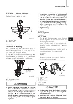
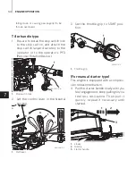
EP/EFT/EPT type
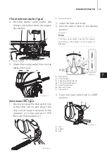
1. To attach the outboard motor to the
boat, use the bolts to secure the out-
board motor brackets on transom
board.
1.
Clamp screw (EP/EFT)
2.
Bolt (8 × 85)
3.
Washer
4.
Nut
a. 30 - 63 mm
View A
ENOW00008-A
z
Mounting bolts should be installed with
the bolt head at inside sur face of the
transom. Mounting bolts installed with the
threaded end at the inside surface of the
transom can cause personal injury.
z
Tighten the bolts sufficiency, otherwise
falling down of outboard could be hap-
pened.
ENON00003-1
Notes
1.
Apply sealing material, such as silicone
sealed between the bolts and the tran-
som board holes before tightening the
bolts.
2. Be sure to tighten the mounting bolt
nuts to the specified torque.
(30 N·m (3.0 kgf·m) 13 ft·lb)
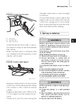
3. For EP / EFT type, drill the holes in
transom board only at left and right of
lower side of clamp bracket, and
attach outboard motor with supplied
bolts.
For EPT type, drill the holes in transom
board at 4 points up and down, right
and left, and attach outboard motor
with supplied bolts.
ENOM00840-0
ENOW00100-B
Be careful not to loop the remote control
cables to a diameter of 406 mm (16 in) or
less. Otherwise, it affects the durability of
the cable.
CAUTION
4
1
2
3
3
a
ENOF00308-2
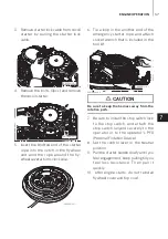
193
187
275
188
64
36
18
18
18
18
51
194
152
㱵
11
12-
㱵
10
ENOF00305-0
2. Remote control device
installation
CAUTION
Summary of Contents for MFS 15E EF
Page 1: ...O W N E R S M A N U A L MFS 15E Original instructions MFS 9 9E MFS 20E OB No 003 11144 2AH1...
Page 6: ......
Page 8: ...11 TROUBLESHOOTING 77 12 ACCESSORIES KIT 79 13 PROPELLER TABLE 80...
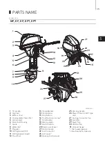
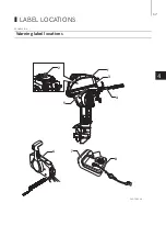
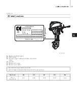
Page 17: ...17 4 LABEL LOCATIONS ENOM00019 A Warning label locations 1 2 8 7 5 6 3 4 ENOF01204 4...


