background image

SERVICE MANUAL

OIL

WASH

OIL LEVEL

B

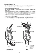
Summary of Contents for TLDI 40

Page 1: ...SERVICE MANUAL OIL WASH OIL LEVEL B...

Page 2: ...Chapter 1 Specifications 1 Specifications Table 1 3 2 Outline Dimensions 1 4 3 Background on TLDI 1 6 1...

Page 3: ...1 2...

Page 4: ...m Idling 700 rpm Full throttle fuel consumption approx 17 L Hr 4 5 US gal Hr Starting system Electric starter motor Intake system Reed valve Scavenging system 5 port loop Exhaust system Through hub Lu...

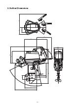
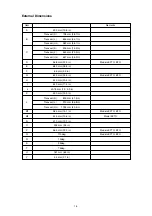
Page 5: ...1 4 2 Outline Dimensions M 1 M 2 P N O S G H I Q D F C B J Y R U L K T A E S...

Page 6: ...EFTO EFO E 680 mm 26 8 in F 85 mm 3 3 in G 623 mm 24 5 in Models EFTO EFO H 520 mm 20 5 in I 440 mm 17 3 in J 30 75 mm 1 2 3 0 in K 490 mm 19 3 in Transom S 800 mm 31 5 in L Transom L 910 mm 35 8 in T...

Page 7: ...of fuel mixture injection timing and ignition timing to maximize combustion efficiency in the TLDI 50 engine The result is better fuel economy smaller size and greater power in a two stroke engine 2 A...

Page 8: ...e homogenized change to ensure the fuel mixture is distributed uniformly throughout the combustion chamber when operating in the high speed range to ensure maximum combustion efficiency L CDI charge c...

Page 9: ...ear on the flywheel in order to detect crankshaft position and transmit the information to the ECU Water Temperature Sensor WTS Positioned on the water jacket installed on the cylinder the water tempe...

Page 10: ...ail u from there it is injected into the combustion chambers The fuel regulator i regulates components t through u in order to maintain gasoline at a differential pressure of 80 kPa 11 4 psi Any exces...

Page 11: ...through the air filter q and used as the air intake when injecting the pressurized gasoline into the combustion chamber pressurized by the air compressor w The air regulator r regulates components w a...

Page 12: ...compressor u Ports r t and y serve to lubricate the engine s pistons while port 7 lubricates the air compressor TLDI includes a recirculation system in which the excess oil from the air compressor u i...

Page 13: ...1 12...

Page 14: ...g Information 1 General Precautions for Servicing 2 3 2 Specifications and Standards Used in Servicing 2 4 3 Lists of Points for Applying Sealant Adhesive and Lubrication 2 10 4 Torque Table 2 16 5 Sp...

Page 15: ...2 2...

Page 16: ...g lubricating with oil or grease packing parts and components and connecting wiring and piping Also ensure there are no blockages in fluid lines 1 When reassembling parts requiring numerous nuts and b...

Page 17: ...Engine block Reed valve stopper Lift height 9 3 to 9 5 mm 0 366 to 0 374 in Fails to close is worn or damaged Reed valve 1 1 15 Ambient temperature Ignition coil 12 5 k 15 Ambient temperature ECU Low...

Page 18: ...abnormally higher than standard value 2 Remove carbon from piston crown and cylinder head surfaces and clean exhaust gas bypass valve No longer conforms to standard value Replace with new part Valve...

Page 19: ...ar and cracks Damage to bearing Wear on lip of oil seal Damage to bearing Shaft run out Wear on lip of oil seal Battery Output Brush length wear limit Commutator under cut wear limit Commutator diamet...

Page 20: ...lower surface lip areas show wear cracks or damage Replace with new assembly When depth of wear is 0 1 mm 0 004 in or more Replace with new shaft Replace with new shaft 0 4 mm 0 016 in or more Repair...

Page 21: ...d value for resistance Operating condition check for clicking sound when 12 volts is applied to the terminal Measured value for resistance Measured values of resistance between connectors Tilted up 13...

Page 22: ...en parts no longer conform to standard values Replace with new parts When parts no longer conform to standard values Replace with new parts When parts no longer conform to standard values Replace with...

Page 23: ...il pump for drive gear Oil pump for driven gear Cylinder crankcase mating surface Water temperature sensor Spark plug gaps Advancer arm Throttle cam Clutch Ball joint gap Cable joint clutch Starter mo...

Page 24: ...l seal in crankcase head Lip area on oil seal in crankcase head Confirm thickness of coating O ring Plug seat and high tension cored Sliding surface Sliding surface Sliding surface Sliding surface Sli...

Page 25: ...bly Adapter hose joint Cable Terminal grommet FFP upper grommet FFP lower grommet Pipe grommet Gear case Gear B nut Propeller shaft housing Propeller shaft housing O ring Propeller shaft oil seal Prop...

Page 26: ...urfaces Both inner and outer surfaces Both inner and outer surfaces Both inner and outer surfaces Apply after cleaning all grease from threading Lower inner surface Lip surface Spline surface Tapered...

Page 27: ...hrust plate Mounting bolt upper Mounting bracket Tilt stopper Motor cover Filler lid hinge upper Hook lever Hook lever bushing Hook lever seal ring Filler lid seal rubber PT T Section PT T cylinder pi...

Page 28: ...ease Sliding surface Sliding surface Sliding surface Thread Spline surface Sliding surface Sliding surface Sliding surface Sliding surface Sliding surface Sliding surface Shaft surface Use the specifi...

Page 29: ...o 21 1 9 to 2 1 kg m 14 to 15 drive shaft housing Bevel gear B Nut bevel gear B M12 40 to 58 4 to 6 kg m 29 to 44 Stern bracket Nylon nut 7 8 24 to 26 2 4 to 2 6 kg m 17 to 19 Mount rubber upper Bolt...

Page 30: ...older 3T5 72815 0 O ring setting tool 24 3T5 72863 0 For installing O rings on the fuel injectors Piston ring wrench 353 72249 0 For installing and removing the piston rings Piston pin tool 345 72215...

Page 31: ...alling flywheel Needle bearing puller kit 3C8 72700 0 For removing and installing gear case needle bearing and propeller shaft housing Spring pin tool A 345 72227 0 For removing and installing spring...

Page 32: ...0 03 90 4 5 When finished measuring turn the lever to position B open to relieve internal pressure then remove adapter B from the measuring valve 0 5 0 1 0 MPa Label Valve assembly Valves for measuri...

Page 33: ...y nut Installing Pulley Nut 1 Apply thread lock Three Bond 1342 to the thread area 2 Screw the pulley nut onto the crankshaft by hand 3 Install the engine s magneto key then install the crankshaft hol...

Page 34: ...en wrench 3B7 72787 0 4 Insert the three collars 3T5 72895 0 between plate C 3T5 72893 0 and the already joined plates A and B 5 Using a 19 mm socket wrench turn the bolt 3T5 72894 0 until the drive p...

Page 35: ...t Piston Slider 3T5 72871 0 Installing Air Compressor Piston 1 Apply sufficient amount of LOR 101 and 2 stroke engine oil mixed on a 1 3 ratio to the exterior of the piston the interior of the piston...

Page 36: ...mbly 2 Air Hose Assembly 3T5 10088 0 Clamp 1 12 3T5 10087 0 Installed at two locations on hose connecting air compressor to air rail assembly 3 Clamp 29 64 3T5 10091 0 Installed at two locations on ho...

Page 37: ...2 24...

Page 38: ...nspecting Engine Oil Systems 3 3 3 Inspecting Fuel Systems 3 3 4 Inspecting Compression System 3 4 5 Inspecting Gear Case Area 3 5 6 Washing Procedure 3 6 7 Inspecting Cooling System 3 6 8 Inspecting...

Page 39: ...ttery cables Battery Mountings fluid spec gravity levels Wear bending Propeller chipping on blades slipping of cushion rubber Gear oil Replace Replenish or change oil check for water leakage Water pum...

Page 40: ...repeat the same air bleeding procedure used on the oil pump 3 Inspecting Fuel System Replacing Engine Fuel Filter q Fuel filter Detachable type w High Pressure Fuel Filter Disposable type Refer to ma...

Page 41: ...does not affect compression readings Measure the compression for all cylinders Confirm that all compression readings conform to specifications Results and Steps to Take Repair or replace components as...

Page 42: ...ove the upper oil plug w and sufficiently drain the oil Insert the gear oil container spigot e into the lower oil plug hole and squeeze the container until oil overflows from the upper oil plug hole F...

Page 43: ...ling System Thermostat test Place the thermostat into a suitable container and add either cold or warm water Heat the water in the container and confirm that the thermostat valve operates when the tem...

Page 44: ...Inspection Procedure Make sure oil seals 5 are installed facing in the proper direction y 5 replace with new components if worn or damaged Replace with new one Replace with new one Replace with new o...

Page 45: ...ing procedure 9 Inspecting Air Rail Pressure Refer to the description for w Pressure Gauge Assembly listed under section 5 Special Tools in Chapter 2 Servicing Information With the outboard engine ins...

Page 46: ...ssembling Power Unit 1 Power Unit 4 2 1 Removing Power Unit 4 3 2 Installing Power Unit 4 5 2 Peripheral Parts 4 6 1 Electrical System 4 6 2 Air Supply System 4 10 3 Fuel System 4 20 4 Oil Pump 4 29 5...

Page 47: ...1 Power Unit 4 2...

Page 48: ...ctors Fuel hose remove from strainer inlet P Type Disassemble the following components i Wire harness connectors 3 o Throttle cable from advancer arm 0 Gearshift cable from gearshift arm 2 Water hose...

Page 49: ...hoist to suspend the power unit while keeping it in the horizontal position w Remove crankcase head Remove with caution by gently inserting a flathead screwdriver in the groove Inspect the following...

Page 50: ...ankcase head Place power unit on to engine base Referring to section 1 assemble power unit in the reverse order of the procedures described there Take care that none of the wiring or hoses gets caught...

Page 51: ...ion sensor Remove the following component w Flywheel nut Remove the following component e Flywheel Remove the following components r Alternator Lighting coil output lead 3 plugs Exciting coil output l...

Page 52: ...eviation for the engine control unit Remove the following components q ECU connector While pressing down on hook remove by prying gently with a flathead screwdriver w Rubber mount bolt type H630 at 3...

Page 53: ...athead screwdriver and pulling out u Bullet connectors for ignition coils Remove the following components i FFP connector Remove by pressing down on hook and pulling out connector FFP abbreviation for...

Page 54: ...4 9 0 1 3 2 Removing Ignition Coil and Rectifier Regulator Remove the following components 0 Ignition coil 1 1 Ignition coil 2 2 Ignition coil 3 3 Rectifier regulator...

Page 55: ...e of the fuel valve e located on the air rail q to release pressure from the fuel lines 3 After loosening the plug t on the upper section of the vapor separator r in order to release pressure loosen t...

Page 56: ...essor bolts at 3 locations Remove the following components y Air compressor u Drive belt Inspecting Drive Belt Replace in cases where even the slightest defect is found Check for wear and damage Check...

Page 57: ...4 12 Air Compressor Configuration AIR COMPRESSOR 1 2 3 4 4 5 6 7 8 9 10 11 13 12...

Page 58: ...d damage 6 Piston Wear and damage Check outer diameter of piston 7 Piston ring Measure piston ring end gap 8 Connecting rod Confirm smooth operation 9 Big end bearing Confirm smooth operation 10 Reed...

Page 59: ...nsert the crank pin in the big end of the connect ing rod and install by gently moving the crank shaft Replace with new one Prior to inserting piston apply heat resistant grease LOR 101 and genuine en...

Page 60: ...e the following components Air filter Hose Band lead wire Position the air filter intake opening as shown in the figure Take care not to mistake the top and bottom and front and back sections of the r...

Page 61: ...ect the hose joint on the compressor side e Cooling water outlet hose r Fuel return hose t Air discharge hose y Cooling water inlet hose Remove the following components u Bolt type H865 at 2 locations...

Page 62: ...Air Rail Assembly Configuration 1 2 3 4 5 6 7 8 9 4 17...

Page 63: ...oblems are detected Clogged regulator strainer Clean if foreign matter is present Wear deterioration and damage on pressure hose Replace with new one if problems are detected 5 Air regulator Wear dete...

Page 64: ...ssemble the following components q Fuel regulator w Hose clamp Refer to Chapter 2 5 in chapter e Air regulator r Collar t Plate y Bolt u Clamp Special tool Crimping pliers 3T5 72864 0 Replace with new...

Page 65: ...l System Disassembling Fuel Hose Assembly Remove the following components q Fuel hose assembly w Lead wire band at 2 locations e High pressure fuel filter r Bolts at 2 locations t Connections to FFP y...

Page 66: ...w Detach the following hoses e Vapor discharge hose r Vapor return hose t Fuel inlet hose Remove the following components y Bolt type H630 at 2 locations u Fuel outlet hose Hold a container in place t...

Page 67: ...Configuration Inspecting Vapor Separator No Components Points to check 1 O rings Wear deterioration and damage 2 Float valve Wear deterioration and damage 3 Float Presence of cracks Contamination by...

Page 68: ...tions Rubber mounts at 2 locations Disassembling FFP Assembly FFP abbreviation for fuel feed pump Remove the following components q FFP connector w Hose joint e Fuel return hose r Vapor return hose t...

Page 69: ...4 24 Blue Yellow y i o 8 r 3 q 1 2 t 0 u u w e e 7 8 5 6 5 4 FFP Configuration...

Page 70: ...place if defects are detected 4 O rings 5 FFP Case Clogging by foreign matter and water 6 FFP assembly Dirt and foreign matter on lower intake port Cracks and damage on upper and lower plastic section...

Page 71: ...ipe grommet 1 FFP 2 Lower grommet t FFP case 0 Upper case The position for t in relation to 1 is shown in the figure to the right Place 0 on top and check posi tion Grease to apply q and 2 Genuine eng...

Page 72: ...acer washer W5 6 Cable covering 7 Bolt type H510 Torque 2 6 to 3 5 N m 0 27 to 0 36 kg m 2 0 to 2 6 lb ft Take care not to pinch cable when closing cover Attach cable to terminal by pressing firmly do...

Page 73: ...locations Washer Rubber mounts Collars e Fuel hose r Fuel return hose t Vapor return hose y High pressure fuel hose u FFP cable connector cable assembly Secure the FFP cable connector to the cylinder...

Page 74: ...pipe 4 Remove the following components q Oil level sensor cable w Bolt type H630 e Oil tank Remove the following components q Bushing w Oil pump driven gear Remove from power unit as shown in the fig...

Page 75: ...cylinder Clamp Install the oil filter on the bracket Install the following components Insert the oil tank into the lower rubber mount Connect the oil level sensor Secure the oil pipe using the clamp...

Page 76: ...pect the following components q Throttle link rod w TPS link rod e Oil pump link rod Inspect the following components Throttle link rod snap TPS link rod snap Oil pump link rod snap Check for wear and...

Page 77: ...ts q TPS assembly w Screw type 420 panhead at 3 locations Washers Collars Remove the following component q TPS assembly Refer to chapter 5 when conducting electrical inspections Never loosen small scr...

Page 78: ...Disassemble the following components Bolt type H625 at 8 locations Clamp q Air box cover Remove the following components w Bolt type H625 at 2 locations q Throttle body assembly r Bolt type H625 at 1...

Page 79: ...ions Assembling Air Box and Throttle Body Assemble in the reverse order of disassembly u Bolt type H625 at 12 locations Replace with new one Replace with new one Grease to apply Interacting surfaces o...

Page 80: ...3 Disassembling Engine Block Cylinder and Crankcase Assembly Air Compressor Line check valve To Air Rail 4 35...

Page 81: ...Piston and Crankshaft 4 36...

Page 82: ...5 at 14 locations Inspecting Engine Anode Inspect the following component q Engine anode Replace when excessively worn When removing the 8 mm bolts loosen in sequence starting from the highest embosse...

Page 83: ...e using 240 to 400 sandpaper in a figure eight pattern Once surface is repaired finish using 600 sandpaper Clean using a scraper or brush Take care not to scratch any surfaces that are being cleaned U...

Page 84: ...lt type H625 at 2 locations for lower head Lower head Crankcase Remove by prying gently along the grooves with a flathead screwdriver If the crankshaft is stuck to the crankcase disengage by tapping l...

Page 85: ...that they enclose pulley then install collars r t and y Apply grease to the tip and the thread area u Remove the pulley by tightening the bolt u 19 mm Special tool Drive pulley puller assembly 3T5 728...

Page 86: ...omponent w Piston pin Position w against piston pin then holding the opposite side by hand tap lightly on w with a hammer to remove pin Take care not to apply force to the connecting rod when using th...

Page 87: ...e 0 007 mm 0 0008 in or more 0 00028 in Standard value Service limit 17 00 mm 0 67 in Depends on clearance with pin Standard value Service limit 0 08 to 0 12 mm Replace when 0 21 mm 0 003 to 0 005 in...

Page 88: ...n 2 mm Replace when 2 mm 0 08 in 0 08 in or more Standard value Service limit Within 0 05 mm Replace when 0 05 mm 0 002 in 0 002 in or more Pressing the ring on the piston crown place in ring gauge Us...

Page 89: ...ng Position piston to connecting rod then place piston pin tool against pin and tap lightly with a hammer to install After installation install the other piston pin clip Special tool Piston pin tool 3...

Page 90: ...or to completing assembly of the crankshaft Install thrust plates at 2 locations Line up the bearing knock position Lining up position of upper bearing Gently move the upper bearing to confirm it is c...

Page 91: ...9 to 4 3 Ib ft M8 partial torque 12 to 15 N m 1 2 to 1 5 kg m 8 7 to 10 9 Ib ft M8 full torque 29 to 34 N m 3 0 to 3 5 kg m 22 to 25 Ib ft Replace with new one Replace with new one Degrease all mating...

Page 92: ...ion pipe Hose clips at 4 locations Caution Insure proper installation of the check valve inside the hose Tighten in the order of the embossed numbers Partial torque 3 9 to 5 9 N m 0 4 to 0 6 kg m 2 9...

Page 93: ...4 48...

Page 94: ...Chapter 5 Installing and Inspecting Electrical Components 1 Wire Routing 5 2 2 Wiring Diagram 5 8 3 Assembly 5 17 4 Inspection 5 22 5...

Page 95: ...Clamp 6 5 87P 3T4 06972 0 Clamp 6 5 47 5P 309 06972 0 Clamp 6 5 47 5P Air Hose Assembly Lower motor cover PTT PTT Pass wiring and small hose between cylinder head and air hose 309 06972 0 Refer to Sol...

Page 96: ...Clamp 8 5 85P 3T5 06971 0 1 high tension cable Clamp 8 5 70P 3T5 06972 0 Clamp 6 5 47 5P Note Wind the clamp underneath the L nipple to prevent 1 high tension cable from contacting the L nipple 309 06...

Page 97: ...5 4 MAGNETO...

Page 98: ...5 5 Battery EFO TYPE Starter motor ELECTRIC PARTS...

Page 99: ...5 6 SWITCH BOX F Type Br Br B B P Sb R R R R Y G L R Y W G G Cable color abbreviations B Black Br Brown G Green L Blue Lg Light green P Pink R Red Sb Sky blue W White Y Yellow...

Page 100: ...5 7...

Page 101: ...P L L L Y Y Y R W F1 F2 F3 A1 A2 A3 I1 I2 I3 Y R R W Y W R W Y B R W Lg R R W R W Lg W B R B W Or Or B W B W Or Or B G B W Sb Sb P P R Y R Y Y R Y R G R G R B B G G R W R L L Lg Lg Br Br Y Y W W B B O...

Page 102: ...G Lg Lg Y R Y R G R G R R R Y Y W W B B R R P P Or Or Lg Lg B B W Y UP Sb R P DN B Br R R G L OFF ON START ON VARIABLE IDLE G G Br Br Br L L R R G NO G COM F N R R Y NO Sb P Sb P G G Y Y R Y R R R B B...

Page 103: ...Y Y R W F1 F2 F3 A1 A2 A3 I1 I2 I3 Y R R W Y B R W Y W R W Lg R R W R W Lg W B R B W Or Or B W B W Or Or B G B W Sb Sb P P R Y Gr Y R Or G R W B B G G G G G G R W R L L Lg Lg Br Br Y Y W W B B B Or Or...

Page 104: ...5 11 27 34 29 28 31 32 26 30 Switch Box B Br R R G L OFF ON START ON VARIABLE IDLE G G L L W W Y Y L B Y W R R P R Sb R R Or Y R W G R Lg G B B Sp P R R Sp P A R Y B Br Br Br C R R R R Y Y G G B PUSH...

Page 105: ...R W F1 F2 F3 A1 A2 A3 I1 I2 I3 Y R R W Y W R W Y B R W Lg R R W R W Lg W B R B W Or Or B W B W Or Or B G B W Sb Sb P P R Y Gr Y R Or G R W B B G G G G G G R W R L L Lg Lg Br Br Y Y W W B B B Or Or Lg...

Page 106: ...5 13 23 29 24 26 27 22 25 Switch Box B Br R R G L OFF ON START ON VARIABLE IDLE G G L L W W Y Y L B Y W R R R R Or Y R W G R Lg G B B P Sp R A R Y B Br Br Br C R R R R Y Y G G B PUSH...

Page 107: ...ly 32 PT T switch 11 Starter solenoid 33 Tachometer 12 PT T solenoid switch A 34 Meter lead wire 13 PT T solenoid switch B 35 Trim sender 14 Fuel injector 36 Trim meter 15 Air injector 37 Water pressu...

Page 108: ...round cable 9 Fuse holder assembly 26 Cable assembly C 10 Starter solenoid 27 Tachometer 11 PT T solenoid switch A 28 PT T switch 12 PT T solenoid switch B 29 Beeper Buzzer 13 Fuel injector 30 Light a...

Page 109: ...e 7 Crank position sensor 22 Cable assembly C 8 ECU 23 Tachometer 9 Fuse holder assembly 24 Beeper Buzzer 10 Starter solenoid 25 Light assembly 11 Fuel injector 26 Main switch 12 Air injector 27 Lanya...

Page 110: ...solenoid Cable Cap Starter Solenoid Green Cable Starter Solenoid Cable Ground Cable q Pre Assembly step 1 Attach the cable clamp fuse holder plate and rubber mount to the bracket w Pre Assembly Step 2...

Page 111: ...reen lead PT T solenoid PT T solenoid ground cable Rectifier Regulator r Pre Assembly Step 4 Past the fuse holder red lead PT T solenoid ground cable and starter solenoid green lead through the hole i...

Page 112: ...enoid ground cables on bolt A A and the cable clamp on bolt B B Rectifier regulator Starter motor wGround cable eOil level sensor qCable assembly qCrank position sensor Magneto coil q u Assembly Step...

Page 113: ...und cable Battery cable Battery cable Oil level sensor Magneto coil Cable cap Also pass fuse holder red lead through the cable cap Cable cap wPT T i Assembly Step 3 q Install the battery cables w Inst...

Page 114: ...PT T A B View B View A Clamp anchor o Assembly Completed Note The sections of clamp shaded in diagonal lines indicate how the lines coming from above are to be gathered together in a downward directio...

Page 115: ...insulation tester w The tester needle moving represents an On reading and not moving represents an Off reading The contain approximate values for the 1 k range Note that values will vary depending on...

Page 116: ...ttached to the plate so that they conform to the designated range e To remove excessive carbon buildup on the commutator select a sandpaper in the 500 to 600 range r Inspect the armature insulation Wh...

Page 117: ...5 24...

Page 118: ...6 Chapter 6 Disassembly Inspection and Reassembly Lower Unit 1 Configuration 6 2 2 Disassembly 6 4 3 Inspection 6 7 4 Reassembly 6 9...

Page 119: ...6 2 1 Configuration GEAR CASE DRIVE SHAFT...

Page 120: ...6 3 GEAR CASE PROPELLER SHAFT...

Page 121: ...downward motion Drainning Gear oil Refer to section on inspecting gear case contained in Chapter 3 Inspection and Maintenance Special tool Spring pin tool A 345 72227 0 2 Disassembly Caution Begin th...

Page 122: ...pin snap ring u Clutch pin q Propeller shaft w Bevel gear C e O ring r Clutch t Clutch pin snap ring y Push rod i Propeller shaft housing Remove the following components r Clutch y Push rod 0 Clutch...

Page 123: ...A Bevel gear A bearing Bevel gear C Removal Procedure 1 Insert r onto spline q 2 Attach t to w 3 Turn t to loosen nut w and remove 4 Remove w 5 Remove q q Drive shaft w Bevel gear B e Gear case r Beve...

Page 124: ...shing of bevel gears A B and C and backlash Wear on bearings for bevel gears A and C Play between clutch and spline Misalignment of drive shaft Wear on spline area Wear contact surface of needle rolle...

Page 125: ...345 72723 0 y O ring 332 60002 0 u Collar 353 72245 1 i Plate 3B7 72729 0 Backlash Reading And Corresponding adjusting shim sizes Notes Example Shim size mm Location 0 1 0 3 0 5 Between lower pump cas...

Page 126: ...e spline and tapered surface area Assembling Propeller Shaft and Clutch Assemble in reverse order of the disassembly procedure Direction of Clutch Clutch pin snap rings Special tool Clutch pin snap to...

Page 127: ...opper Once installation is completed operate the cam rod to confirm that it moves freely up and down Spring pins must never be reused Apply gear oil to the O rings Install so that the spring pin does...

Page 128: ...n the oil seals r While taking care not to scratch the lip area of the oil seals r insert the drive shaft into the pump case Carefully fit the protruding side of the pump case liner w into the recessi...

Page 129: ...2 locations on the gear case marked with the then install the remaining bolts Spring pin Special tool Spring pin tool B 345 72228 0 Replace with new one Torque 19 to 21 N m 1 9 to 2 1 kg m 14 to 15 I...

Page 130: ...7 Chapter 7 Power Trim and Tilt 1 Configuration 7 2 2 Names of Parts 7 3 3 Troubleshooting 7 4 4 Disassembly and Assembly 7 12...

Page 131: ...ual valve Spool Relief valve UP Relief valve DN Valve seat assembly A Valve seat assembly B Inlet valve Inlet valve Motor Breaker Solenoid switch DN Battery 12V 100AH Solenoid switch UP Switch Oil Pum...

Page 132: ...lve 2 Relief valve UP 3 Relief valve DN 4 Spool 5 Check valve upper chamber Valve seat assembly A 6 Check valve lower chamber Valve seat assembly B 7 Manual valve 8 Seal washer 9 Inner Collar 10 Sprin...

Page 133: ...king connectors electrical shorts and severed lines Does the motor turn over when the battery is directly connected Are the switches operating properly Is the wiring connected properly Has operating o...

Page 134: ...to CH q Are there any signs of oil leakage CH o Is the manual valve closed properly CH 0 Is oil level normal CH 1 Is the proper oil being used CH 2 Has air entered the hydraulic system CH 3 Is the pis...

Page 135: ...lled on the engine s electric bracket and touch the plug against the connector on the red cable If the PT T operates it indicates a faulty PT T switch UP Sky blue DN Pink The alternative is to use an...

Page 136: ...leaks operate the PT T unit and look for signs of oil leakage on the surrounding water s surface In cases where oil leaks are discovered in the PT T unit or the cylinder it will be necessary to condu...

Page 137: ...ure and check oil level again The PT T should normally contain 550 ml 18 7 fluid ounces of oil CH 2 Use only the specified types of oil The oil specified for this engine is ATF Dexron made by Japan Oi...

Page 138: ...of the system A single air bleeding operation is not sufficient to remove air that has found its way into the center of the system This must be removed by repeating the air bleeding operation over a p...

Page 139: ...rd or trim upward c Falls when the motor is turned off b Stops part way up e Won t move at all g Takes too long to tilt downward or trim downward f Stops part way up Inspect the relief valve UP CH 9 D...

Page 140: ...ot affected by foreign matter Also check to see if the filter is clogged when checking the relief valve UP CH 0 Confirm that spool moves freely when pressed by hand Check backup ring for wear and dama...

Page 141: ...7 Ib in Apply oil to O rings 2 Relief valve UP Bolt torque 1 2 to 1 4 kg m 8 7 to 10 1 Ib ft Apply oil to O rings 3 Relief valve DN Apply oil to O rings 4 Spool valve Apply oil to exterior of spool an...

Page 142: ...Chapter 8 Tiller Handle Type 1 Installing Gearshift Lever Assembly 8 2 2 Installing Switchbox Assembly 8 3 3 Installing Handle Assembly 8 4 4 Installing Handle To Engine 8 4 8...

Page 143: ...R Clamp 6 5 47 5P Use 3 gearshift lever stoppers Gearshift lever stopper plate not required Clamps should be tightened together Insert washers on both sides of gearshift lever B and be sure to bend sp...

Page 144: ...the power trim and tilt switch cover and install together with the power trim and tilt switch using the screws 921503 5206 6 Install the PT T switch cover with the embossed UP letters on the stop swi...

Page 145: ...handle holder After installation confirm that there is no excessive pulling or bending stress applied to the cable by moving the handle up and down 4 Installing Handle To Engine 1 Pass the cable assem...

Page 146: ...Chapter 9 Troubleshooting 1 Troubleshooting Tables 9 2 2 TLDI Self Diagnosing Functions 9 14 9...

Page 147: ...and indicators is described in a separate section Symptom Item Self diagnosable points Beeps Warning indicator A oil Warning indicator B water temp Warning indicator C battery 1 Starter motor dead or...

Page 148: ...2 2 6 2 2 7 2 2 8 2 2 9 2 2 10 2 2 11 Cause Remedy see chapter on Servicing Information for specs Shift to neutral position Recharge or replace battery Check battery terminal and cable condition Check...

Page 149: ...but won t start 2 2 Fuel system 2 3 Air system 2 4 Electrical system Low fuel pressure in air rail normal 0 6 to 0 64 MPa High fuel pressure in air rail normal 0 6 to 0 64 MPa 87 to 93 psi Low air pre...

Page 150: ...ing lock Short circuit in stop switch Carbon buildup or damage to fuel injector Faulty sparkplugs Replace Inspect piping and connectors for damage Inspect and repair Replace Refer to steps 2 3 9 and 2...

Page 151: ...system 3 1 Power head 3 2 Fuel system Sparkplug cap Crank position sensor ECU Self diagnosing function indicates low abnormal battery voltage Self diagnosing function indicates faulty components Self...

Page 152: ...fails to close is worn or damaged Faulty cylinder head or engine base gasket Loose head bolts or crankcase bolts Fuel is low or empty in tank Air vent is clogged Water in fuel filter Fuel filter is cl...

Page 153: ...lectrical system 5 1 5 2 5 3 5 4 6 1 Engine compression Low fuel pressure in air rail normal 0 6 to 0 64 MPa 87 to 93 psi High fuel pressure in air rail normal 0 6 to 0 64 MPa Low air pressure in air...

Page 154: ...d Disfiguration or wear of throttle link components Scratches on piston or cylinder liner Carbon buildup in combustion chamber Excessive wear or sticking of piston ring Refer to steps 2 2 12 Refer to...

Page 155: ...h main switch 6 1 Power head 6 2 Air system 6 3 Fuel system 6 4 Electrical system 7 1 Outboard engine 8 1 Electrical system Faulty compression Low air pressure in air rail High air pressure in air rai...

Page 156: ...ncorrect loading position Overloading of boat Problem with shape of boat Faulty electrical contact on main switch or severed line in harness Faulty contract on stop switch or severed line in harness F...

Page 157: ...ndicator C battery 9 Poor acceleration at full throttle or sudden drop down to idling speed 10 Unable to exceed 3000 rpm at full throttle or suddenly drops and stays at 3000 rpm 9 1 Electrical control...

Page 158: ...water pump Faulty thermostat Cooling water path clogged Faulty battery Faulty charging coil Faulty wiring to charging coil Faulty battery cables or connectors Faulty rectifier regulator Faulty TPS fau...

Page 159: ...t log display Mode 4 fault log delete 1 Glossary of Self Diagnosis Terminology Key switch On the EP models the key switch is located on the remote control box On the EF models it is located on the swi...

Page 160: ...enabled when the engine is not running The self diagnosing function can be terminated during any of the steps listed below by simply turning the key switch to the Off position Note that the optional...

Page 161: ...s Refer to Engine Operating Hours Table Self diagnosing Mode 3 Fault Location and Fault Log Display This Mode displays after one short beep sounds the fault location and fault log for first incident a...

Page 162: ...diagnosing Mode 4 Fault Log Delete Even when in Mode 3 can be enabled by releasing the stop switch lock and pressing the key for approximately 3 seconds until 3 short beeps are emitted This deletes th...

Page 163: ...ing water temp high Cooling water temp abnormally high Battery voltage abnormally low Battery voltage low Battery voltage high Battery voltage abnormally high Faulty TPS 2 idle position Faulty TPS Fau...

Page 164: ...000 6 000 7 000 800 900 1 000 2 000 3 000 4 000 5 000 6 000 7 000 800 900 1 000 2 000 3 000 Indicator A On On On On On On On On On On On On On On On On On On On On On On On On On On On On On On On On...

Page 165: ...nition coil Oil level low Battery voltage low Battery voltage abnormally low Faulty CPS 3 1 TPS 4 idling position error 2 TPS idling position error Faulty 1 TPS 1 TPS power supply high 1 TPS power sup...

Page 166: ...function or failure take remedial measures In the case of injectors Replace with new injector If the fault remains check the wiring In the case of ignition coils If only one is indicated as faulty rep...

Page 167: ...fter the beep buzzer stops sounding disconnect the stop switch lock w Wait approximately 5 to 10 seconds 7 seconds to be exact then pull the red knob on the stop switch for 0 5 second or less and rele...

Page 168: ...Chapter 10 Test Run and Inspection After Servicing 1 Test Run Tank and Test Propeller 10 2 2 Inspection 10 3 10...

Page 169: ...ng and overflow systems be installed Over periods of continued use the tank water gradually becomes contaminated by the waste discharged from the engine This waste which eventually coats the interior...

Page 170: ...o perform a breaking in of the engine in order to properly seat the sliding surfaces of the various parts in cases where pistons piston rings piston pins and cylinders have been replaced Perform the v...

Page 171: ...10 4...

Page 172: ...Chapter 11 Installation on Boat and Test Run 1 Precautions for Using This Engine 11 2 2 Remote Control System 11 3 3 Gauges and Battery 11 4 4 Operating the Engine 11 6 11...

Page 173: ...ntil it stops approx 32 The cable that moves first is the gearshift cable A distance of 10 mm 0 4 in is equivalent to about nine threads on the joint After fully loosening the screw Philips 420 instal...

Page 174: ...rn the cable joint on the end of the remote control cable in order to line up the cable joint with the gearshift arm and advancer arm pins Secure in place using the locknut then insert the arm pin and...

Page 175: ...ire 50 to 80 Fitting plate Dashboard 1 0 6 7 2 5 3 4 Cut mounting holes to bore size 85 mm Cut mounting hole to bore size 52 5 mm 85 mm 3 4 in 52 5 mm 2 1 in Tachometer Trim gauge 12P 6P 4P Selector R...

Page 176: ...ubing is the one that connects to the positive terminal Caution 3 Wiring Diagram for Remote Control Unit and Gauges Be sure to carefully read the warning label on the battery prior to use Never discon...

Page 177: ...spect for the presence of air Bleed hoses if necessary Do this by loosening the air vent screw on the oil pump and bleeding until all air has been removed from the piping Note that the air may not ble...

Page 178: ...following oil force feeding procedure for engines that are new that have been serviced and reassembled that have run out of oil or that have been stored for long periods a As shown in the figure to t...

Page 179: ...engine speed increases progressively in the following increments 700 rpm 800 900 800 700 800 900 rpm Prior to turning the main switch key to ON make sure that the throttle grip has been set to START f...

Page 180: ...essively in the following increments 700 800 900 800 700 800 900 rpm Prior to turning the main switch key to On make sure that the neutral warm up lever has been set to fully closed position Mistakenl...

Page 181: ...er the oil falls below the designated level approx 350 ml The warning consists of flashing indicators accompanied by 3 short beeps at 2 minute intervals Note The warning is displayed whether the gears...

Page 182: ...to only to cooling water temperature and is not related to fuel combustion and lubrication oil related warnings The following procedure is required to cancel the engine regulation mode once it has bee...

Page 183: ...marks One of the following three types of warnings is output depending on the cause seriousness of the trouble 1 Warning indicators only flash 2 Warning indicators flash and engine speed is regulated...

Page 184: ...oration All rights reserved No part of this manual may be reproduced or transmitted in any form or by any means without the express written permission of Tohatsu Corporation ServiceData_cover_e_071214...

Page 185: ...Address 5 4 3 chome Azusawa Itabashi ku TOKYO 174 0051 Japan Facsimile 03 3966 2951 Phone 03 3966 3117 No 00321050 1 0209012600 Printed in Japan...

Reviews: