


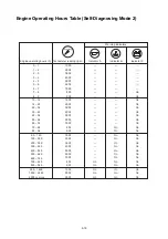


9-11
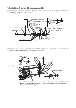
6-1-6.
6-2-1.
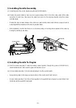
6-3-1.
6-3-2.
6-3-3.
6-3-4.
6-3-5.
6-3-6.
6-3-7.
6-3-8.
6-3-9.
6-3-10.
6-3-11.
6-4-1.
6-4-2.
6-4-3.
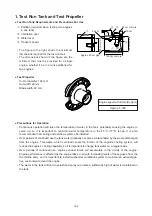
7-1-1.
7-1-2.
7-1-3.
7-1-4.
7-1-5.
7-1-6.
7-1-7.
7-1-8.
7-1-9.
8-1-1.
8-1-2.
8-1-3.
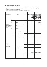
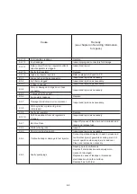
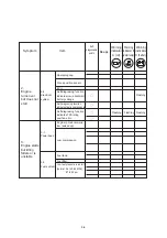
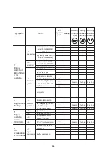
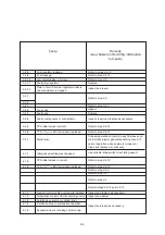
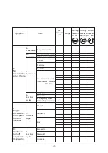
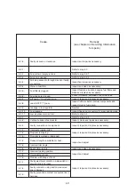
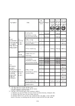
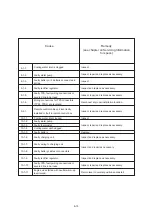
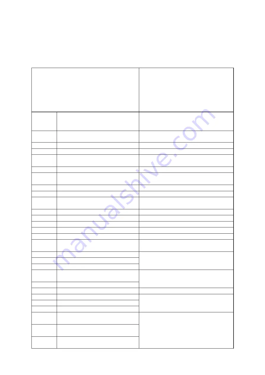
Cause
Remedy
(see chapter on Servicing Information
for specs.)
Faulty oil seal on crankcase.
Fuel is low or empty in tank.
Air vent is clogged.
Air being sucked in through cracks or faulty
connectors.
Water in fuel filter.
Fuel filter is clogged.
Fuel lines are clogged.
Lift pump (*1) not functioning.
Leak in FFP (*1) case.
Leakage in fuel regulator.
Fuel leakage.
Low air pressure in air rail.
Carbon buildup in fuel injector.
Faulty connection or component.
Incorrect propeller pitch.
Propeller is slipping.
Propeller is warped or damaged.
Transom length unsuitable for boat.
Incorrect trim angle.
Boat bottom is dirty.
Incorrect loading position.
Overloading of boat.
Problem with shape of boat.
Faulty electrical contact on main switch or
severed line in harness.
Faulty contract on stop switch or severed
line in harness.
Faulty ground line contact or severed line in
harness.
Inspect and repair as necessary.
Refer to step 2-3.
Refer to step 2-2-1.
Refer to step 2-2-2.
Inspect and repair as necessary.
Inspect and clean as necessary.
Inspect fuel tank, boat and engine fuel filters and
clean and replace as necessary.
Check for twisted, flattened or bent fuel lines.
Inspect, repair and replace as necessary.
Inspect rubber seal on internal components and
inspect electric fuel pump.
Replace.
Inspect lines and connectors for wear and damage.
Refer to step 2-3.
Refer to step 2-4-3.
Inspect, clean and replace as necessary.
Inspect, repair and replace as necessary.
Inspect, repair and replace as necessary.
Inspect and adjust.
Inspect and clean as necessary.
Inspect and adjust.
Inspect, repair and replace as necessary.
Summary of Contents for TLDI 40
Page 1: ...SERVICE MANUAL OIL WASH OIL LEVEL B...
Page 3: ...1 2...
Page 5: ...1 4 2 Outline Dimensions M 1 M 2 P N O S G H I Q D F C B J Y R U L K T A E S...
Page 13: ...1 12...
Page 15: ...2 2...
Page 37: ...2 24...
Page 47: ...1 Power Unit 4 2...
Page 57: ...4 12 Air Compressor Configuration AIR COMPRESSOR 1 2 3 4 4 5 6 7 8 9 10 11 13 12...
Page 62: ...Air Rail Assembly Configuration 1 2 3 4 5 6 7 8 9 4 17...
Page 69: ...4 24 Blue Yellow y i o 8 r 3 q 1 2 t 0 u u w e e 7 8 5 6 5 4 FFP Configuration...
Page 81: ...Piston and Crankshaft 4 36...
Page 93: ...4 48...
Page 97: ...5 4 MAGNETO...
Page 98: ...5 5 Battery EFO TYPE Starter motor ELECTRIC PARTS...
Page 100: ...5 7...
Page 117: ...5 24...
Page 119: ...6 2 1 Configuration GEAR CASE DRIVE SHAFT...
Page 120: ...6 3 GEAR CASE PROPELLER SHAFT...
Page 146: ...Chapter 9 Troubleshooting 1 Troubleshooting Tables 9 2 2 TLDI Self Diagnosing Functions 9 14 9...
Page 171: ...10 4...


