


e
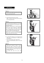
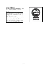
Cooling Water Indicator
A water temperature warning is displayed and the
engine automatically reduces speed whenever the
cooling water rises above the designated level.
Remedial Action:
Remarks:
Remarks:
r
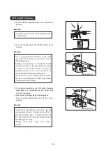
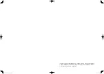
Battery Level Warning
• The battery warning indicator flashes when the
battery level falls below 10V. All 3 warning
indicators flash when battery voltage rises to
abnormally high levels.
• The battery warning indicator flashes and engine
speed is automatically reduced to the 2,800 to
3,200 rpm range when a battery fault occurs or
there are faulty battery cable connections. Note
that the engine will completely shut down in the
case of serious faults.
Remedial Action:
• Inspect and properly install battery connectors.
• Recharge battery.
• Replace battery.
This warning applies to only to cooling water
temperature and is not related to fuel combustion
and lubrication oil related warnings.
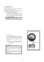
The following procedure is required to cancel the
engine regulation mode once it has been activated,
regardless of whether temperature has returned to
normal.
Table No. 1: lower to idling speed.
Table No. 2: turn off engine.
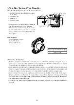
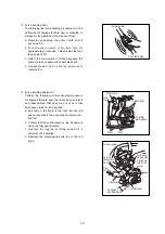
Quickly move the boat to a safe harbor, set the
throttle grip or remote control lever to the low
speed range and set the gearshift or remote
control lever to the Neutral (N) position. Confirm
whether cooling water is discharged with sufficient
force from the water inspection hole; then turn off
the engine. Remove any trash or plastic material
from the vicinity of the gear case.
11-11
1
0
6
7
2
5
3
4
Water warning indicator
Light warning indicator
+
-
Battey
warning
indicator
1
0
6
7
2
5
3
4
+
-
Tachometer on EPTO series
Switchbox on EPTO and EPTO series
No.
1
2
Sensor setting
Regulated rpm
Threshold
Over threshold
2,800 to 3,200 rpm
700 to 900 rpm
Summary of Contents for TLDI 40
Page 1: ...SERVICE MANUAL OIL WASH OIL LEVEL B...
Page 3: ...1 2...
Page 5: ...1 4 2 Outline Dimensions M 1 M 2 P N O S G H I Q D F C B J Y R U L K T A E S...
Page 13: ...1 12...
Page 15: ...2 2...
Page 37: ...2 24...
Page 47: ...1 Power Unit 4 2...
Page 57: ...4 12 Air Compressor Configuration AIR COMPRESSOR 1 2 3 4 4 5 6 7 8 9 10 11 13 12...
Page 62: ...Air Rail Assembly Configuration 1 2 3 4 5 6 7 8 9 4 17...
Page 69: ...4 24 Blue Yellow y i o 8 r 3 q 1 2 t 0 u u w e e 7 8 5 6 5 4 FFP Configuration...
Page 81: ...Piston and Crankshaft 4 36...
Page 93: ...4 48...
Page 97: ...5 4 MAGNETO...
Page 98: ...5 5 Battery EFO TYPE Starter motor ELECTRIC PARTS...
Page 100: ...5 7...
Page 117: ...5 24...
Page 119: ...6 2 1 Configuration GEAR CASE DRIVE SHAFT...
Page 120: ...6 3 GEAR CASE PROPELLER SHAFT...
Page 146: ...Chapter 9 Troubleshooting 1 Troubleshooting Tables 9 2 2 TLDI Self Diagnosing Functions 9 14 9...
Page 171: ...10 4...


