

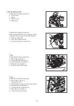


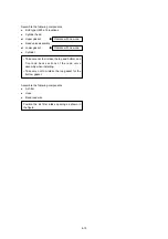


4-11
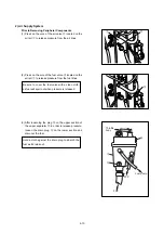
t
q
u
w
y
e
r
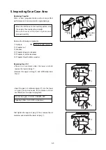
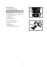
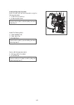
Removing Air Compressor
Remove the following components.
q
Detach the oil pipe on the compressor side.
w
Detach recirculation pipe on the compressor side.
e
Detach cooling water pipe on compressor side.
r
Remove air hose on compressor side.
t
Compressor bolts: at 3 locations
Remove the following components.
y
Air compressor
u
Drive belt
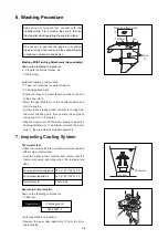
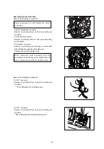
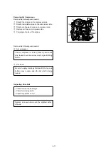
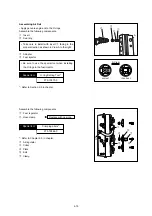
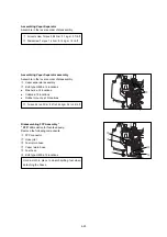
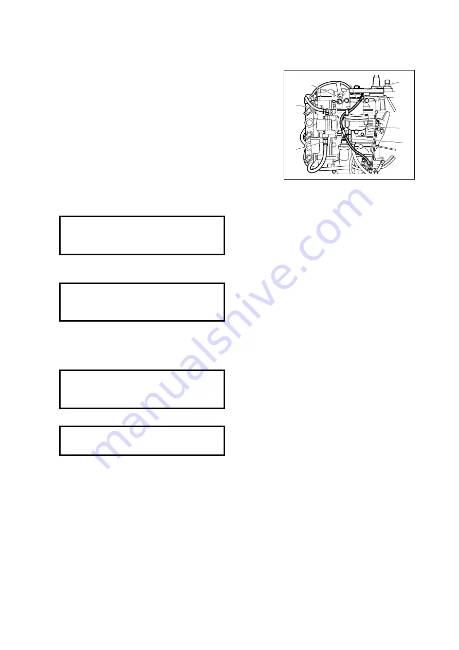
Inspecting Drive Belt
Replace in cases where even the slightest defect
is found.
• Check for wear and damage.
• Check for missing teeth.
• Check for presence of oil.
Be sure to apply markings that identify the top and
bottom sides in cases when the drive belt is being
reused.
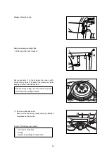
The air compressor is held in place by two knock
pins, these should be removed with a gentle tilting
motion.
Summary of Contents for TLDI 40
Page 1: ...SERVICE MANUAL OIL WASH OIL LEVEL B...
Page 3: ...1 2...
Page 5: ...1 4 2 Outline Dimensions M 1 M 2 P N O S G H I Q D F C B J Y R U L K T A E S...
Page 13: ...1 12...
Page 15: ...2 2...
Page 37: ...2 24...
Page 47: ...1 Power Unit 4 2...
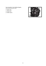
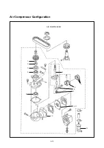
Page 57: ...4 12 Air Compressor Configuration AIR COMPRESSOR 1 2 3 4 4 5 6 7 8 9 10 11 13 12...
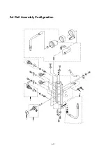
Page 62: ...Air Rail Assembly Configuration 1 2 3 4 5 6 7 8 9 4 17...
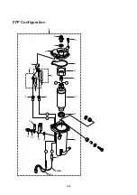
Page 69: ...4 24 Blue Yellow y i o 8 r 3 q 1 2 t 0 u u w e e 7 8 5 6 5 4 FFP Configuration...
Page 81: ...Piston and Crankshaft 4 36...
Page 93: ...4 48...
Page 97: ...5 4 MAGNETO...
Page 98: ...5 5 Battery EFO TYPE Starter motor ELECTRIC PARTS...
Page 100: ...5 7...
Page 117: ...5 24...
Page 119: ...6 2 1 Configuration GEAR CASE DRIVE SHAFT...
Page 120: ...6 3 GEAR CASE PROPELLER SHAFT...
Page 146: ...Chapter 9 Troubleshooting 1 Troubleshooting Tables 9 2 2 TLDI Self Diagnosing Functions 9 14 9...
Page 171: ...10 4...


