


4-19
w
q
e
r
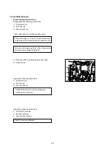
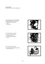
A
A View
correct
incorrect
w
q
e
r
t
u
y
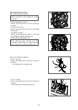
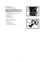
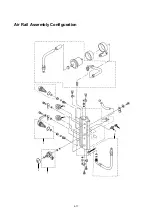
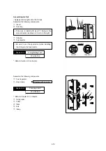
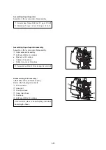
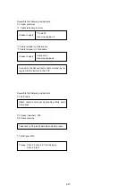
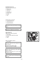
Assembling Air Rail
• Apply genunie engine oil to the O-rings.
Assemble the following components.
q
Insert
w
Seal ring
e
Adapter
r
Fuel injector
*: Refer to Section 2-5 in chapter.
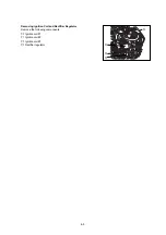
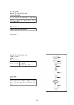
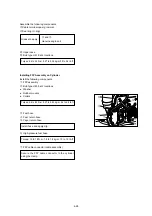
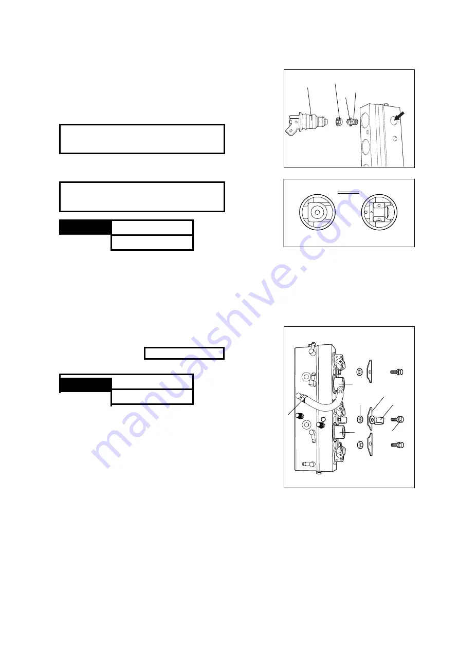
Assemble the following components.
q
Fuel regulator
w
Hose clamp
*
*: Refer to Chapter 2-5 in chapter.
e
Air regulator
r
Collar
t
Plate
y
Bolt
u
Clamp
Special tool
Crimping pliers*
3T5-72864-0
Replace with new one.
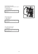
Special tool
O-ring Setting Tool*
3T5-72870-0
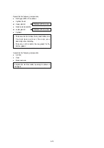
• Be sure to use the special tool when installing
the O rings in the fuel injector.
• Take care to install with insert
q
facing in the
proper direction as shown in View A to the right.
Summary of Contents for TLDI 40
Page 1: ...SERVICE MANUAL OIL WASH OIL LEVEL B...
Page 3: ...1 2...
Page 5: ...1 4 2 Outline Dimensions M 1 M 2 P N O S G H I Q D F C B J Y R U L K T A E S...
Page 13: ...1 12...
Page 15: ...2 2...
Page 37: ...2 24...
Page 47: ...1 Power Unit 4 2...
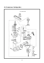
Page 57: ...4 12 Air Compressor Configuration AIR COMPRESSOR 1 2 3 4 4 5 6 7 8 9 10 11 13 12...
Page 62: ...Air Rail Assembly Configuration 1 2 3 4 5 6 7 8 9 4 17...
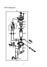
Page 69: ...4 24 Blue Yellow y i o 8 r 3 q 1 2 t 0 u u w e e 7 8 5 6 5 4 FFP Configuration...
Page 81: ...Piston and Crankshaft 4 36...
Page 93: ...4 48...
Page 97: ...5 4 MAGNETO...
Page 98: ...5 5 Battery EFO TYPE Starter motor ELECTRIC PARTS...
Page 100: ...5 7...
Page 117: ...5 24...
Page 119: ...6 2 1 Configuration GEAR CASE DRIVE SHAFT...
Page 120: ...6 3 GEAR CASE PROPELLER SHAFT...
Page 146: ...Chapter 9 Troubleshooting 1 Troubleshooting Tables 9 2 2 TLDI Self Diagnosing Functions 9 14 9...
Page 171: ...10 4...


