


4-26
!0
q
!3
r
!1
!2
t
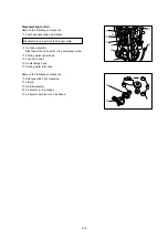
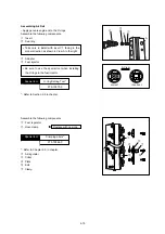
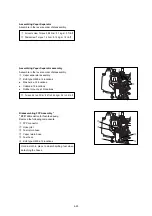
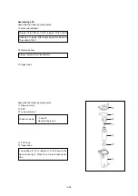
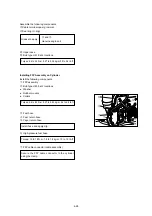
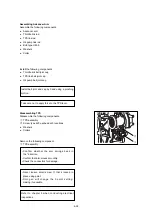
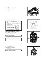
Assembling FFP
Assemble the following components.
i
Hose joint adapter
o
Metal washers
!0
Upper case
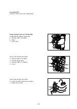
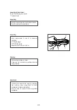
Assemble the following components.
q
Pipe grommet
!1
FFP
!2
Lower grommet
t
FFP case
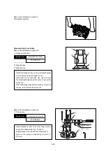
!0
Upper case
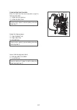
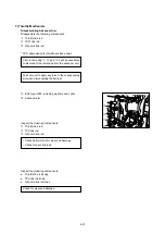
The position for
t
in relation to
!1
is shown in the
figure to the right. Place
!0
on top and check posi-
tion.
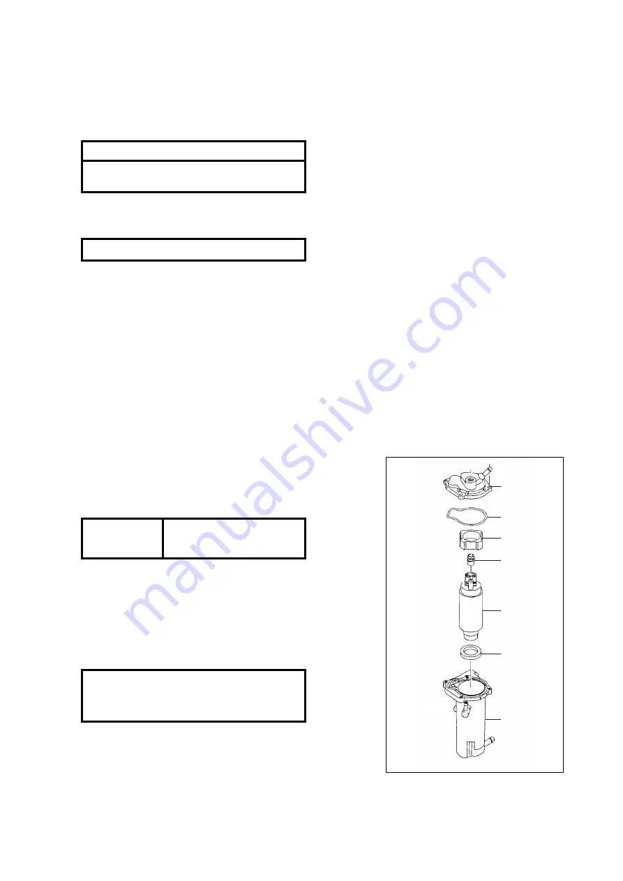
Grease to apply
q
and
!2
Genuine engine oil
Always replace after disassembly.
Torque: 14 to 16 N-m: 1.4 to 1.6 kg-m: 10 to 12 Ib-ft
Adhesive to apply after degreasing thread area:
Three Bond 1342
Summary of Contents for TLDI 40
Page 1: ...SERVICE MANUAL OIL WASH OIL LEVEL B...
Page 3: ...1 2...
Page 5: ...1 4 2 Outline Dimensions M 1 M 2 P N O S G H I Q D F C B J Y R U L K T A E S...
Page 13: ...1 12...
Page 15: ...2 2...
Page 37: ...2 24...
Page 47: ...1 Power Unit 4 2...
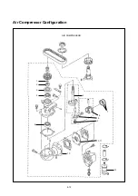
Page 57: ...4 12 Air Compressor Configuration AIR COMPRESSOR 1 2 3 4 4 5 6 7 8 9 10 11 13 12...
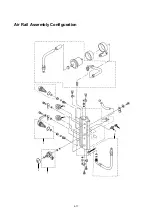
Page 62: ...Air Rail Assembly Configuration 1 2 3 4 5 6 7 8 9 4 17...
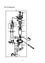
Page 69: ...4 24 Blue Yellow y i o 8 r 3 q 1 2 t 0 u u w e e 7 8 5 6 5 4 FFP Configuration...
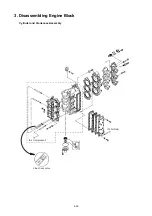
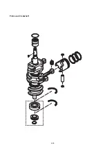
Page 81: ...Piston and Crankshaft 4 36...
Page 93: ...4 48...
Page 97: ...5 4 MAGNETO...
Page 98: ...5 5 Battery EFO TYPE Starter motor ELECTRIC PARTS...
Page 100: ...5 7...
Page 117: ...5 24...
Page 119: ...6 2 1 Configuration GEAR CASE DRIVE SHAFT...
Page 120: ...6 3 GEAR CASE PROPELLER SHAFT...
Page 146: ...Chapter 9 Troubleshooting 1 Troubleshooting Tables 9 2 2 TLDI Self Diagnosing Functions 9 14 9...
Page 171: ...10 4...


