Communication manual TOHO ELECTRONICS INC.
DWG.No. 4B-6829-A
- 7 -
4.4.
Explanation about Codes
■
The following codes other than ⑧BCC will be expressed in ASCII code.
■
See “
” for the detail about ASCII codes.
■
To convert into ASCII code, se
e “
①STX
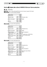
It is a code that is necessary for the receiving side to detect the start of the message. It shall be attached to the start of the character
string to be sent.
② Address
Format = Type 1
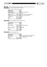
Specifies the device that will be communicated by the upper computer. Address setting value shall serve as the address of this
product.
Format = Type 2
Specifies the channel of the device that will be communicated by the upper computer. Address of the subjected channel shall
be computed by the following formula:
Address = {(Address Setting Value - 1) x 6} + Subjected Channel
Example) Address of channel 4 where address setting value = 5
Address = {(5 - 1) x 6} + 4 = 28
③ Contents of Request
Set the symbol R or W.
R: If the data is to be read from this product
W: If the data is to be written or saved into this product
④ First Identifier
It is a classification symbol (identifier) of the data to be read or written that will be expressed by the 3-digit alphanumeric ASCII code.
See “10. List of Identifiers (Codes).”
⑤ Second Identifier
Format = Type 1
It is used to specify the channel for the data to be specified by the firstidentifier that has been allocated to each channel.
This is not necessary for the data that is not allocated per channel. Do not include it in the request message.
See “
” to check if the second identifier is required or not.
Format = Type 2
This will not be used. Do not include it in the request message.


