10
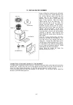
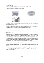
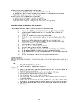
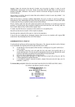
9. INSTALLATION OF THE COLUMN STIFFENER
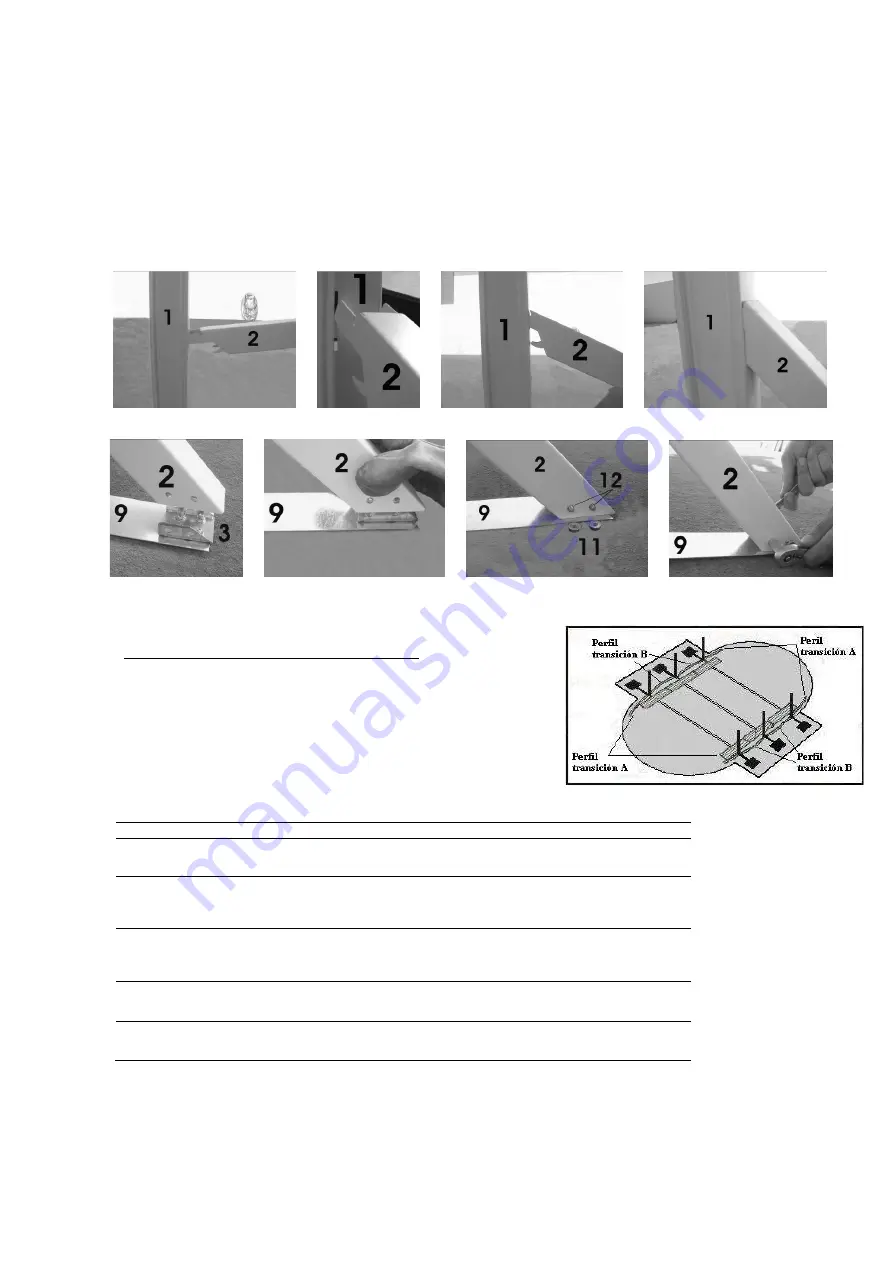
a. Place the stiffener (2) in an almost horizontal position and insert the four flanges on the end of
the stiffener into the grooves in the vertical column (1), photos 11, 12, 13 and 14.
b. Push the stiffener (2) forward until you can see the four flanges inside the vertical column (1), whilst
at the same time moving the lower end of the stiffener towards the angle plate (3) in the base strap,
fit the angle plate (3) into the stiffener (2), photos 15 and 16.
b. Screw the stiffener (2) to the lower plate (3) with two screws (12) and the corresponding nuts
(11). Do not tighten excessively, just enough to ensure secure anchoring, photos 17 and 18.
c. Repeat steps (a) to (c) on the other side of the strap and for each strap.
10. ASSEMBLY OF POOL BASE (PCM)
I n s t a l l t h e c u r v e d t r a n s i t i o n s e c t i o n s
- Each pool model has t wo, t hree or four different t ypes
of c urv ed lower sect ions. T he s ect ions are given a
number depending on their pos it ion, f ig. 2. Consult t he
t able below t o c hoose the t ype and quant it y of lower
s ect ions suit able f or your pool.
Fig. 2
Transition sections table
Transition section A
Transition section B
Measurement
549x366 cm.
850.015 x 4
not applicable
± 1.420 mm x 4
640x366 cm.
850.021 x 4
850.019 x 2
± 1.130 mm x 4
± 1.430 mm x 2
731x366 cm.
850.021 x 4
850.017 x 4
± 1.132 mm x 4
± 1.130 mm x 4
914x457cm.
850.019 x 4
850.019 x 4
± 1.430 mm x 8
12x457cm.
850.019 x 4
850.019 x 8
± 1.430 mm x 12
photo
11
photo
12
photo
13
photo
14
photo
15
photo
16
photo
17
photo
18


