9.2 Switching box
9-4
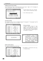
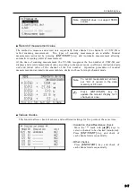
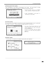
1. From the monitor screen, go to “Channel
setting” and then to “Measurement mode”.
■
Measurement mode setting
Select Multi-channel mode on the Measurement mode screen. Refer to “5.6: Switching of
measurement mode” for more detail of setting procedure.
■ Channel setting
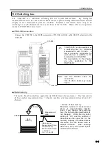
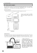
Five channels can be set for one CSW-5B (channel 0 to channel 4). It is possible to set 50
channels for 10 switching boxes at maximum.
■ Box number setting
Box number of CSW-5B is set by TC-32K.
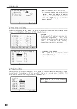
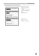
○ Channel indication
A channel number consists of 2-digit
numbers. The upper digit is a box
number, and the lower digit is a channel of
CSW-5B. The left screen is the monitor
screen displayed when a CSW-5B with the
box number 5 is connected.
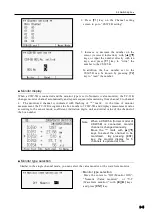
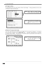
2. Select “Multi channel mode”.
In multi-channel mode, TC-32K
automatically
recognizes
the
connected CSW-5B and displays
monitor screen. If no switching
box is connected, the left screen
appears. Even if no switching box
is connected, program settings
(sensor mode, coefficient, etc.) for
each channel are available.
Note
1. Press
[F2]
key on the Monitor screen to go
to “Channel Setting”.
Summary of Contents for TC-32K
Page 1: ...O p e r a t i o n M a n u a l TC 32K HANDHELD DATA LOGGER...
Page 8: ...Chapter 12 Error Message 12 1 Explanations and countermeasures for error messages 12 2...
Page 9: ...Chapter 1 Overview 1 1 Overview 1 2 1 2 Features 1 2 1 3 Details about each part 1 3...
Page 22: ...2 5 Operation outline 2 10 memo...
Page 23: ...Chapter 3 Sensor Connection 3 1 Sensor connection 3 2...
Page 65: ...5 10 Measurement auxiliary setting 5 28 memo...
Page 78: ...6 5 Recording in data memory and CF card 6 13 memo...
Page 86: ...7 7 Remote measurement 7 8 memo...
Page 98: ...8 7 Factory setting 8 12 memo...
Page 127: ...11 4 Outside drawing 11 8 11 4 Outside drawing Unit mm...
Page 128: ...Chapter 12 Error Message 12 1 Explanations and countermeasures for error messages 12 2...


