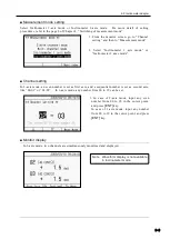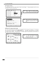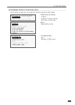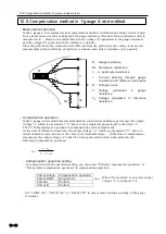
10.1 Wire connection of strain gauge
10-2
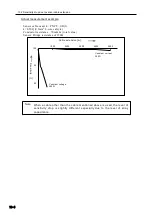
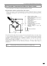
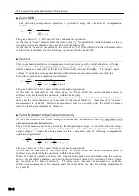
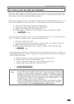
Automatic compensation of lead wire is not available even if you perform
measurement with Comet B. Similar to Comet A, the measurement value must
be compensated separately. For more detail, refer to
“10.3 Complete
Compensation Method of Strain
”.
10.1 Wire connection of strain gauge
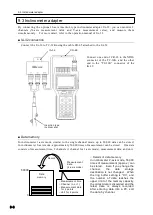
This section explains connection methods of strain gauges available by TC-32K. The next section
shows decreasing rate of sensitivity due to extension of strain gauge.
■ 1-gauge 4-wire method
This method uses a 4-core lead wire for connection of a strain gauge. It eliminates gauge factor
drop due to lead wire resistance and measurement error caused by contact resistance. It also
allows elimination of initial unbalance caused by the lead wire including thermal output caused by
the temperature change of the lead wire.
For quarter bridge 3-wire method, use of a lead wire as thick and short as possible is recommended
for minimizing errors caused by the lead wire resistance. However, with the 1 gauge 4-wire
method, thin lead wires and/or connectors can be used for connection and extension. As a result,
it allows more efficient wiring works, prevents wiring errors, and reduces costs for strain
measurement by re-use of lead wires.
■ Quarter bridge 2-wire method
Internal fixed resistors of the instrument are used for configuring a bridge circuit except the active
gauge (strain gauge which detects strain).
Resistance of the lead wire connecting the strain gauge enters serially only in the active gauge arm
of the bridge circuit. If a thin and/or long lead wire is used, initial unbalance may become too
large to be balanced, and thermal output caused by the temperature change of the lead wire is mixed
with strain reading. Also, temperature compensation for the strain gauge is not possible. For
more accurate measurement, the use of quarter bridge 3-wire method is recommended.
This quarter bridge 2-wire method can be measured in sensor mode of quarter bridge 3-wire
(1G3W) by connecting B and C of the terminal block. However, the TC-32K does not support this
way formally.
■ Quarter bridge 3-wire method
A 3-core lead wire is used for connection to compensate the influence of lead wire in quarter bridge
2-wire method. Since the resistance of the lead wire enters also in the fixed resist or arm of the
bridge circuit as well as in the active gauge arm, affection of initial unbalance caused by the lead
wire resistance is eliminated and temperature compensation for the lead wire is also possible.
However, temperature compensation for the strain gauge is not possible.
■ Half bridge method
Internal fixed resistors are used for two arms of bridge circuit. Strain gauges of the same lot
should be used, and a 3-core wire is used for connection. Temperature compensation for the strain
gauge and for the lead wire is possible at the same time, and affection of initial unbalance caused by
the lead wire is eliminated.
■ Full bridge method
Strain gauges configure all 4 arms of bridge circuit without using internal fixed resistors. This
method is used for transducers, and also for measurement of torque or bending where large output is
preferred, but not often used for general stress measurement works. When the bridge circuit is
configured in the area where the strain gauges are mounted, initial unbalance and affection of
temperature can be eliminated even when the lead wire is extended.
Note
Summary of Contents for TC-32K
Page 1: ...O p e r a t i o n M a n u a l TC 32K HANDHELD DATA LOGGER...
Page 8: ...Chapter 12 Error Message 12 1 Explanations and countermeasures for error messages 12 2...
Page 9: ...Chapter 1 Overview 1 1 Overview 1 2 1 2 Features 1 2 1 3 Details about each part 1 3...
Page 22: ...2 5 Operation outline 2 10 memo...
Page 23: ...Chapter 3 Sensor Connection 3 1 Sensor connection 3 2...
Page 65: ...5 10 Measurement auxiliary setting 5 28 memo...
Page 78: ...6 5 Recording in data memory and CF card 6 13 memo...
Page 86: ...7 7 Remote measurement 7 8 memo...
Page 98: ...8 7 Factory setting 8 12 memo...
Page 127: ...11 4 Outside drawing 11 8 11 4 Outside drawing Unit mm...
Page 128: ...Chapter 12 Error Message 12 1 Explanations and countermeasures for error messages 12 2...


