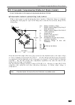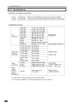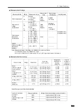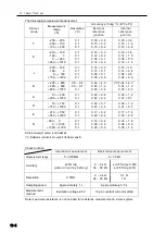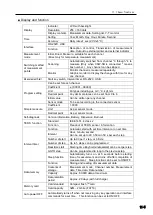
10.2 Sensitivity drop due to sensor cable extension
10-5
■
Measurement by constant current method
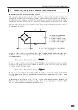
Since the excitation current is kept constant in constant current method, voltage applied to the
transducer is always constant even when the cable resistance changes. Therefore, sensitivity drop
can be ignored.
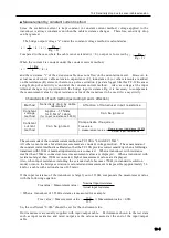
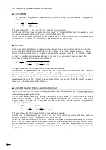
The bridge output voltage “e” under the constant voltage method is calculated as:
e =
× k × ε × ( )
Compared to the case where the cable is not extended (r = 0), ou tp ut is lowered b y
When the current I is constant under the constant current method,
e =
× k × ε
and the resistance “r” of the extension cable does not affect on the calculation result. However, in
actual cases of sensor cable extension, capacitance (C), inductance (L) or other elements are added
on the resistance (R) element, therefore, a pulse excitation type data logger like this TC-32K causes
a slight drop of sensitivity even under the constant current method. Also, as voltage at the input
terminal changes in proportion with the bridge input resistance Rg, it is necessary to compensate
the measurement value by input resistance value of the transducer to be used if we say strictly.
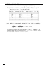
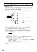
M e t h o d
Sensitivit y dro p b y cable
resistance
Aff ection of tr ansducer input resistance
C o n sta nt
vo lta g e
m et h o d
Approx . -17%/km
f or 0.5mm
2
cable:
( f or in pu t res i
stance 350Ω)
Can be ignored
C o n sta nt
c ur re n t
m et h o d
Can be ignored
Com pensate if required.
True value
= measurement value ×
The sensor mode of the constant current method on TC-32K is “4GAGE C350Ω”.
All other sensor modes for strain measurement are constant voltage method. The sensor mode of
the constant current method is calibrated so that the TC-32K provides correct sensitivity when a full bridge
transducer with 350Ω of nominal input resistance is connected. When a transducer with resistance
smaller than 350Ω is connected, lower measurement values are displayed. When a transducer with
resistance larger than 350Ω is connected, higher measurement values are displayed.
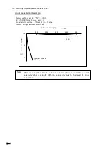
Also, when input resistance including the extended cable becomes 750Ω (in standard resolution
mode) or more, the bridge excitation is saturated and measurement is impossible (approximately 5.6
km for a cable with sectional area of 0.5mm
2
).
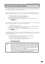
If the input resistance of the transducer is largely out of 350Ω, compensate the measurement value
with the following equation:
True value = Measurement value ×
○ When a
transducer of 355Ω resistance is measured for example:
True value = Measurement value ×
≒
Measurement value × 0.986
So, the coefficient “0.986” should be set for the instrument side.
Our transducers are usually supplied with input/output cable. Performance shown in the test data
such as input resistance and rated output are the values measured at the end of the i nput/output
cable.
Rg
Rg + 2r
E
4
I × Rg
4
Characteristic of each method (excluding C and L affection)
Nominal input resistance (350
Ω)
A c t u a l i n p ut r es is t a nc e
Rg
Rg + 2r
× ( ).
Nominal input resistance
Actual input resistance
350
355
Summary of Contents for TC-32K
Page 1: ...O p e r a t i o n M a n u a l TC 32K HANDHELD DATA LOGGER...
Page 8: ...Chapter 12 Error Message 12 1 Explanations and countermeasures for error messages 12 2...
Page 9: ...Chapter 1 Overview 1 1 Overview 1 2 1 2 Features 1 2 1 3 Details about each part 1 3...
Page 22: ...2 5 Operation outline 2 10 memo...
Page 23: ...Chapter 3 Sensor Connection 3 1 Sensor connection 3 2...
Page 65: ...5 10 Measurement auxiliary setting 5 28 memo...
Page 78: ...6 5 Recording in data memory and CF card 6 13 memo...
Page 86: ...7 7 Remote measurement 7 8 memo...
Page 98: ...8 7 Factory setting 8 12 memo...
Page 127: ...11 4 Outside drawing 11 8 11 4 Outside drawing Unit mm...
Page 128: ...Chapter 12 Error Message 12 1 Explanations and countermeasures for error messages 12 2...

