
10.3 Complete Compensation Method of Strain (Comet)
10-7
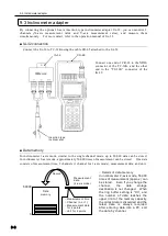
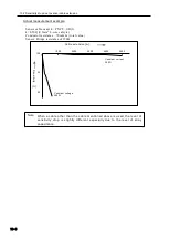
The data header of channel for which Comet A is available is [m].
10.3 Complete Compensation Method of Strain (Comet)
Comet: Abbreviation of Complete Compensation Method of Strain
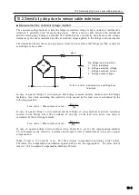
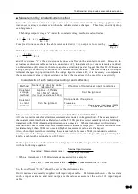
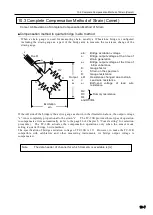
■Compensation method in quarter bridge 3-wire method
When a strain gauge is used for measuring strain, usually a Wheatstone bridge is configured
including the strain gauge as a part of the bridge arm to measure the resistance change of the
strain gauge.
If the AB side of the bridge is the active gauge as shown in the illustration above, the output voltage
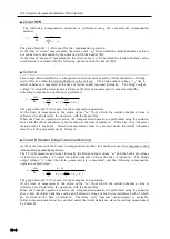
“e” is not completely proportional to the strain “ε”. The TC-32K provides three types of operation
to compensate errors automatically (refer to the page 26 of Chapter 5, “Comet setting” for selection
procedure). The TC-32K activates the compensation operations only when the sensor mode
setting is quarter bridge 3-wire method.
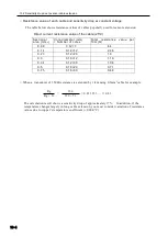
The specification of bridge excitation voltage of TC-32K is 1V. However, to make the TC-32K
compatible with calibrators and other measuring instruments, its bridge output voltage is
compensated.
ein:
Bridge excitation voltage
e:
Bridge output voltage at the time of
strain generation
e
0
:
Bridge output voltage at the time of
initial unbalance
K:
Gauge factor
ε:
Strain on the specimen
R:
Gauge resistance
Δ
R:
Resistance changed due to strain
r:
Lead wire resistance
e
r
:
Both-end voltage of lead wire
resistance
R2
R3
Dummy resistance
R4
and R3=R4
r
R+
Δ
R
r
r
B
C
D
A
R2
R3
R4
ε
Output
e
e
0
e
r
Note
Excitation
ein
Summary of Contents for TC-32K
Page 1: ...O p e r a t i o n M a n u a l TC 32K HANDHELD DATA LOGGER...
Page 8: ...Chapter 12 Error Message 12 1 Explanations and countermeasures for error messages 12 2...
Page 9: ...Chapter 1 Overview 1 1 Overview 1 2 1 2 Features 1 2 1 3 Details about each part 1 3...
Page 22: ...2 5 Operation outline 2 10 memo...
Page 23: ...Chapter 3 Sensor Connection 3 1 Sensor connection 3 2...
Page 65: ...5 10 Measurement auxiliary setting 5 28 memo...
Page 78: ...6 5 Recording in data memory and CF card 6 13 memo...
Page 86: ...7 7 Remote measurement 7 8 memo...
Page 98: ...8 7 Factory setting 8 12 memo...
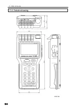
Page 127: ...11 4 Outside drawing 11 8 11 4 Outside drawing Unit mm...
Page 128: ...Chapter 12 Error Message 12 1 Explanations and countermeasures for error messages 12 2...




![Lambrecht Ser[LOG] Operator'S Manual preview](http://thumbs.mh-extra.com/thumbs/lambrecht/ser-log/ser-log_operators-manual_3390951-001.webp)


