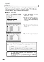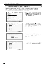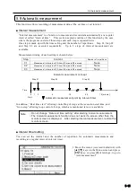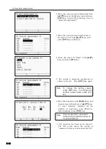
5-10
○
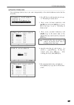
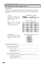
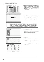
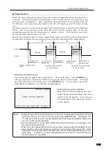
Example of coefficient setting by Cap/RO
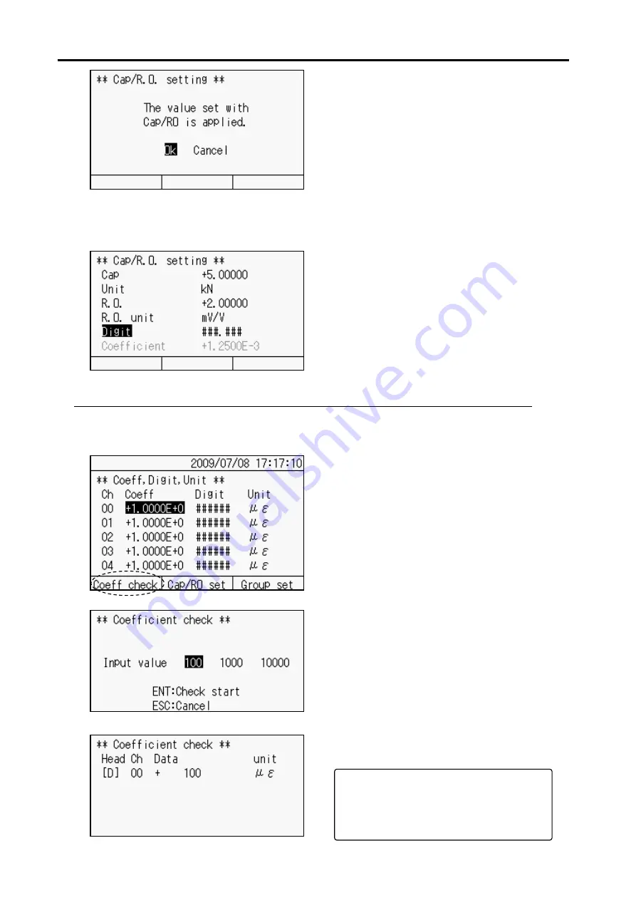
This is an example of setting a load cell with capacity (Cap) of 5kN and rated output
(RO) of 2mV/V.
■
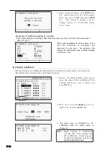
Check of coefficient
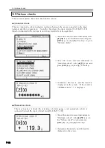
This function allows confirmation whether the set coefficient is appropriate or not based on
the relation between input values and indicated values.
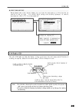
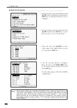
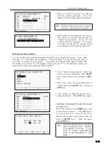
1. On the
“Coefficient, Digit, Unit” screen,
move the cursor to the coefficient of the
channel which you want to check, and
press
[F 1]
key.
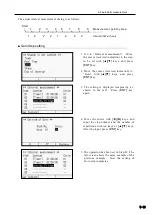
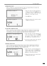
2. Move the cursor with
[
◄][►]
keys to an
input value, and press
[ENT]
key.
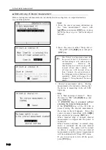
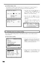
3. The input value is multiplied by the
coefficient and the result value is
displayed.
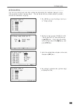
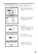
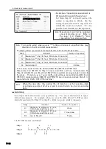
3. After setting all items, press
[ESC]
key.
The screen shown in the left appears.
Move the cursor to
[Ok]
and press
[ENT]
key. The setting is applied, and the
display returns to “Coefficient, Digit,
Unit” screen.
After
setting
a
coefficient,
execute the check function for
the coefficient. It will help you
to prevent troubles caused by
wrong coefficient input.
Note
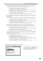
When each parameter is set as shown in the
left, the coefficient is calculated and
displayed in pale gray. By applying this
setting, the indication value is direct reading
of physical value.
Summary of Contents for TC-32K
Page 1: ...O p e r a t i o n M a n u a l TC 32K HANDHELD DATA LOGGER...
Page 8: ...Chapter 12 Error Message 12 1 Explanations and countermeasures for error messages 12 2...
Page 9: ...Chapter 1 Overview 1 1 Overview 1 2 1 2 Features 1 2 1 3 Details about each part 1 3...
Page 22: ...2 5 Operation outline 2 10 memo...
Page 23: ...Chapter 3 Sensor Connection 3 1 Sensor connection 3 2...
Page 65: ...5 10 Measurement auxiliary setting 5 28 memo...
Page 78: ...6 5 Recording in data memory and CF card 6 13 memo...
Page 86: ...7 7 Remote measurement 7 8 memo...
Page 98: ...8 7 Factory setting 8 12 memo...
Page 127: ...11 4 Outside drawing 11 8 11 4 Outside drawing Unit mm...
Page 128: ...Chapter 12 Error Message 12 1 Explanations and countermeasures for error messages 12 2...

