5.5 TEDS sensor
5-12
5.5 TEDS sensor
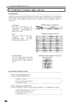
TEDS (Transducers Electronic Data Sheet) is the function allowing the measuring instrument
to automatically recognize parameters quickly without setting errors. An IC chip that stores
parameters including capacity and rated output is installed in a transducer such as load cell or
displacement transducer, and the instrument reads out those parameters.
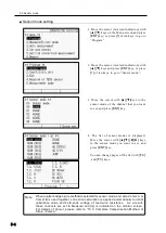
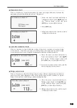
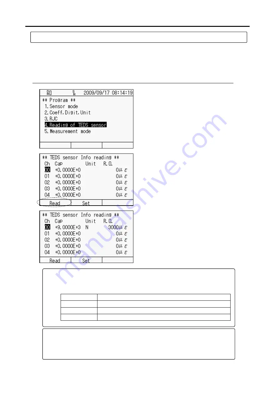
■ Reading of sensor setting
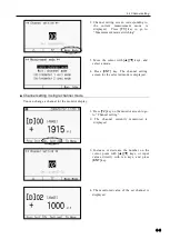
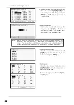
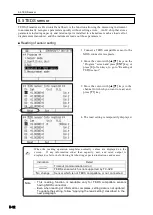
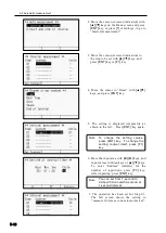
2. Move the cursor with
[▲][▼]
keys on the
“Program” screen and press
[ENT]
key, or
press [
4]
of ten keys, to go to “Reading of
TEDS sensor”.
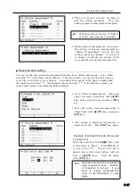
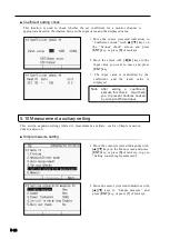
3. Move the cursor with
[▲][▼]
keys to the
channel for which you want to read, and
press
[F1]
key.
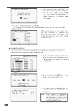
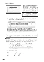
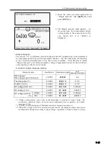
4. The read setting is temporarily displayed.
1. Connect a TEDS compatible sensor to the
NDIS connector receptacle.
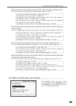
When the reading operation completes normally, values are displayed on the
screen. If any information other than capacity, unit, and rated output is
displayed, refer to the following list showing expected indications and causes:
Indication
Detail
--------
Timeout (communication error)
********
TEDS sensor which is not supported by TC-32K
No change
Sensor which is not TEDS compatible, or not connected
✍
○
This reading function is available only for TEDS compatible sensors
having NDIS connectors.
○
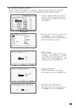
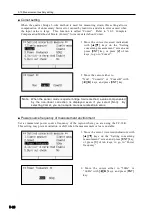
Even when reading of information completes, setting data is not updated.
To update the setting, follow
“Applying the read setting” described in the
next paragraph.
Note
Summary of Contents for TC-32K
Page 1: ...O p e r a t i o n M a n u a l TC 32K HANDHELD DATA LOGGER...
Page 8: ...Chapter 12 Error Message 12 1 Explanations and countermeasures for error messages 12 2...
Page 9: ...Chapter 1 Overview 1 1 Overview 1 2 1 2 Features 1 2 1 3 Details about each part 1 3...
Page 22: ...2 5 Operation outline 2 10 memo...
Page 23: ...Chapter 3 Sensor Connection 3 1 Sensor connection 3 2...
Page 65: ...5 10 Measurement auxiliary setting 5 28 memo...
Page 78: ...6 5 Recording in data memory and CF card 6 13 memo...
Page 86: ...7 7 Remote measurement 7 8 memo...
Page 98: ...8 7 Factory setting 8 12 memo...
Page 127: ...11 4 Outside drawing 11 8 11 4 Outside drawing Unit mm...
Page 128: ...Chapter 12 Error Message 12 1 Explanations and countermeasures for error messages 12 2...

