PLS-601 User's Manual
Document #11696 Page - 9
3.3 TRANSDUCER/CONTROL UNIT INTERFACE CABLE
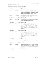
The CONTROL UNIT is interfaced to the TRANSDUCER via a custom made transducer
interface cable. This cable consist of three individually shielded pairs, that has an eight pin female
plug-connector on one end, and a seven pin female MS-type connector on the other end.
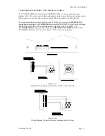
The standard transducer interface cable is wired at the factory to provide an
INCREASING
angular position reading for
CLOCKWISE
rotation of the TRANSDUCER shaft (when looking
into the END of the shaft). The wiring diagram for this cable is shown in Figure 3.3A.
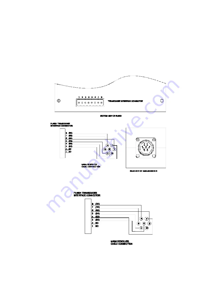
If an
INCREASING
angular position reading for
COUNTER CLOCKWISE
rotation of the
TRANSDUCER shaft is desired, refer to Figure 3.3B for that wiring diagram.
Figure 3.3A
Standard Wiring Diagram (Clockwise transducer shaft rotation)
Figure 3.3B
Wiring Diagram (Counter clockwise transducer shaft rotation)


