PLS-601 User's Manual
Document #11696 Page - 12
3.4 PLS-601 RELAY OUTPUT BOARDS
- Continued
3.4.2 Electromechanical Relay Board
The electromechanical relay board contains a maximum of seventeen electromechanical relays,
each rated at 240 VAC at 10 Amps, or 30VDC at 10Amps. Each relay is configured as SPST,
providing one normally open contact (N.O.) and one normally closed contact (N.C.).
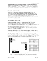
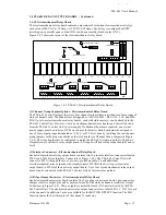
Figure 3.4.2 shows the layout of the electromechanical relay board.
1
2
3
4
5
1
2
3
4
5
P102
P101
A
B
C
D
INPUT
D
H
C
H
B
H
A
H
D
L
C
L
B
L
A
L
P100A
P100B
16 ERR
INT EXT
+12VDC
1
2
3
4
5
6
7
8
9
10
11
12
13
14
15
16
+
-
ENA
NC
NO
C
3
C
NO
6
NC
NO
NC
C
9
NO
C
12
NC
15
C
NO
NC
NO
NC
C
14
NO
NC
C
16
11
C
NO
NO
NC
NC
C
13
8
C
NO
NO
NC
NC
C
10
5
C
NO
NO
NC
NC
C
7
2
C
NO
NO
NC
NC
C
4
MD
C
NO
NO
NC
NC
C
1
MD
Channel Group Jumpers
1
Interface Connectors
2
Relay Output Connectors
3
12DC
Relay 16 Jumper
4
Connector
Output Enable
5
DC Power Source
6
Figure 3.4.2 PLS-601 Electromechanical Relay Board
(1) Channel Group Jumper Options - Electromechanical Relay Board
The PLS-601 Control Unit provides sixty-four channel outputs that are divided into four groups of
sixteen channels each. The channels are designated as A01-A16, B01 - B16, C01 - C16, and D01-
D16. Up to four electromechanical relay boards, each with sixteen relays, can be attached to the
PLS-601 Control Unit. However, only one electromechanical relay board can be directly driven
from the PLS-601 Control Unit’s power supply. If additional boards are required, an external
power supply must be used (see DC Power Source for details). Each board must be assigned to
one of four output groups designated as A, B, C, or D. This is done by installing the two channel
group jumpers in the proper positions on the relay board (see Channel Group Jumpers in Figure
3.4.2). The relay board must be configured to match the PLS-601 output group that will drive it.
Output Group A will drive relay output board A, Group B will drive relay output board B and so
forth.
(2) Interface Connectors - Electromechanical Relay Board
Each electromechanical relay output board contains two 20 pin male interface connectors labeled
P101A and P101B (see Interface Connectors in Figure 3.4.2). The PLS-601 Control Unit will
connect to P101A through the use of a twenty pin ribbon cable. To add additional
electromechanical relay output boards, simply connect P101B of the first (or previous) relay
output board to P101A of the next relay output board. Up to four electromechanical relay output
boards can be connected to the PLS-601 Control Unit by this interface method.
(3) Relay Output Connectors - Electromechanical Relay Board
Each electromechanical relay board contains five 3 pin plug connectors and six 6 pin connectors
that provides two output pins and a common for each of the sixteen channels (see Relay Output
Connectors in Figure 3.4.2). These outputs are normally closed (NC) until activated by the PLS-
601 Control Unit. The electromechanical relay output connectors are labeled (NO C NC) for each
of the channels. In addition, 3 pins are available for the MOTION DETECT function. The MD
function shares the first three pins of the channel 1 connector.


