PLS-601 User's Manual
Document #11696 Page - 13
3.4 PLS-601 RELAY OUTPUT BOARDS
- Electromechanical Relay Board Continued
(4) Relay 16 Jumper Options - Electromechanical Relay Board
Electromechanical Relay 16 may be used as one of the standard channel output relays, or it may be
used as an indication that an error has occurred in the PLS-601 Control Unit. To enable solid state
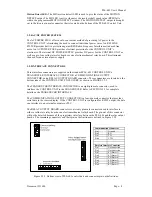
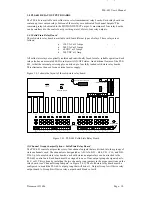
relay 16 as a standard output, connect pins 1 and 2 together of J1 (see Relay 16 Jumper in Figure
3.4.2). To enable solid state relay 16 as an error indicator, connect pins 2 and 3 together of J1.
When solid state Relay 16 is used as an error indicator, it will be active in non error conditions
(ON) and non-active in an error condition (OFF).
(5) Output Enable - Electromechanical Relay Board
Each electromechanical relay board has a 2 pin input connector that implements an OUPTUT
ENABLE function (see "Output Enable Connector in Figure 3.4.2). This connector is labeled
ENA. The ENA pins must be shorted together in order for any of the seventeen electromechanical
relay outputs to be enabled. If this connection is opened, all seventeen electromechanical relay
outputs will be disabled.
(6) DC Power Source - Electromechanical Relay Board
The internal power supply of the PLS-601 Control Unit is capable of only driving one fully loaded
electromechanical relay board. Additional boards must be driven from an external power supply.
To use an external power supply, the jumper labeled INT EXT +12VDC must be placed between
2 and 3 (see DC Power Source in Figure 3.4.2). The external power supply voltage source must
enter the board through the connector labeled (+ - 12DC). Make sure that the positive voltage of
the external supply is attached to the connector pin labeled (+) and that the negative voltage (or
ground) is attached to the connector pin labeled ‘-‘.


