PLS-601 User's Manual
Document #11696 Page - 15
4.1.3 CONNECTING THE RESOLVER TO THE CONTROL UNIT - Continued
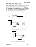
The seven pin female MS-connector is plugged into the mating seven pin male connector located
on the rear of the Resolver.
The eight pin female connector is plugged into the mating eight pin male connector located on the
bottom of the PLS-601 Control Unit (See SECTION 3.2.5).
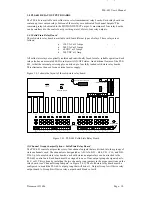
4.1.4 MOUNTING THE RELAY BOARDS
The relay boards are designed to be mounted in a NEMA type enclosure that is suitable for the
environment that the boards will operate within. The enclosure must be shock mounted and be
able to protect the boards from water, oil, dust, and corrosive materials. The boards should not be
exposed to excessive amounts of mechanical shock or vibration. The mounting location should not
be exposed to extreme levels of electromagnetic interference (EMI) that can be induced by
devices such as motor starters and control relays. The operating temperature of the relay boards
has been rated at 32°F to 125°F.
4.1.5 INSTALLING THE AC POWER CORD
An AC Power Cord is provided with each PLS-601 Control Unit. The female end of the Power
Cord should be inserted into the male AC Power Plug located on the side of the Control Unit
enclosure.
4.1.6 POWERING ON THE CONTROL UNIT
The Control Unit requires a clean, stable source of AC Power to operate. See SECTION 3.2 for
the complete AC Power requirements and specifications of the various Control Unit input power
options.
The male end of the AC Power Cord should be inserted into a standard GROUNDING
RECEPTACLE, which has been wired to provide the AC Power requirements specified in
SECTION 3.2.

