PLS-601 User's Manual
Document #11696 Page - 36
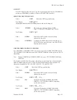
4.4 CHANNEL STATUS GROUP SELECTION
The Channel outputs are divided into four groups of sixteen outputs each - designated A01-A16,
B01-B16, C01-C16 and D01-D16.
The sixteen CHANNEL STATUS LED’s display the status of the sixteen Channel outputs in the
CHANNEL STATUS GROUP indicated by the GROUP LED’s.
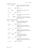
Anytime that the FUNCTION LED is lit, the current CHANNEL STATUS GROUP may be
changed by using the CURSOR utility keys.
The right CURSOR key will rotate the CHANNEL STATUS GROUP to the (i.e. A to B to C to D
to A), while the left CURSOR key will rotate the CHANNEL GROUP to the left (i.e. D to C to B
to A to D).
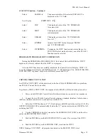
During execution of the SET and TEACH functions, the CHANNEL STATUS GROUP is
automatically set to the CHANNEL GROUP currently being shown on the alphanumeric display.
4.5 ERROR CONDITIONS
By selecting RELAY 16 JUMPER OPTION ‘S’ (see Section 3.4.1), Relay 16 can be used to
provide a hardware indication that one of the following Control Unit error conditions has
occurred:
TRANSDUCER SIGNAL ERROR
CONTROL UNIT MICROPROSSER FAULT
LOSS OF AC POWER
With the ‘S’ option selected, Relay 16 is held normally closed (N.C.) by the Control Unit
hardware. Should any of the Control Unit errors occur, Relay 16 is OPENED to indicate the error
condition.
4.5.1 TRANSDUCER SIGNAL ERROR
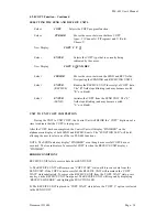
If any of the PLS601-IT Interface Cable wires become disconnected or broken, the following error
indications will be given by the Control Unit:
In DISPLAY MODE
1.
The message ‘TRANSDUCER ERROR’ will be placed on the display
2.
The OUTPUT DISABLE LED will be lit
3.
All PLS601-RE Relay outputs will be dis abled
NOTE: Relay 16 is disabled, regardless of the selected jumper option.
In PROGRAM MODE
1.
POSITION and RPM values will read ‘000’ on the display
2.
The OUTPUT DISABLE LED will be lit
3.
All PLS601-RE Relay outputs will be disabled
NOTE: Relay 16 is disabled, regardless of the selected jumper option.
4.
Normal Control Unit programming will be allowed


