PLS-601 User's Manual
Document #11696 Page - 38
5.0 PLS-601 MODEL 11
The PLS-601 Model 11 features an “Electric Gearbox” function that provides multi-turn capability
for the PLS-601 Model 10, using the standard PLS-TR-1 single turn resolver.
5.1 ELECTRONIC GEARBOX
The ‘ELECTRONIC GEARBOX’ function allows the user to select the total NUMBER OF
TURNS required for the application, which can be any number from 1 to 100. As with the
standard system, the selected SCALE FACTOR determines the resolution of each turn, to a
maximum of 1000. The total SYSTEM RESOLUTION IS 1000 counts/turn for 100 turns or
100,000 turns. Because the number of turns is stored in non-volatile EEPROM memory, the
current POSITION is retained during a loss of power to the Control Unit.
NOTE: Following the loss of power, the system will resume normal operation - providing that the
transducer shaft has not rotated more than 1/2 turn (180 degrees) in either direction. If a 180
degree shaft rotation has occurred during the loss of power, the POSITION will be in error and
have to be reset.
The following sections out line the differences between the operation and programming of the
Model 10 and Model 11 Control Units.
5.2 “MEMORY FULL” CONDITION
The Model 11 Control Unit provides a maximum of 476 LOBES for each of the 4 PROGRAMS.
When making a modification to an existing LOBE in memory or in applications which require a
large number of LOBES, a MEMORY FULL condition may be reached. ‘MEMORY FULL’ will
be displayed during the SET or TEACH functions to indicate the MEMORY FULL condition. The
system will continue with its normal operation, but will not allow further entry or modification of
LOBES.
The MEMORY FULL condition may be cleared by pressing the CLEAR key while ‘MEMORY
FULL’ is being displayed. The Control Unit will free up room in memory by eliminating any
unused LOBES.
WARNING: The process of compressing the memory is very rapid and is not perceptible to the
user. However, during this time, the outputs will be frozen at their current states. To AVOID
MACHINE MALFUNCTION, IT IS STRONGLY RECOMMENDED THAT THE OUTPUTS
BE DISABLED DURING THIS PROCESS.
5.3 SELECTING THE NUMBER OF TURNS (MASTER MODE)
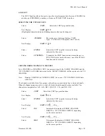
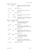
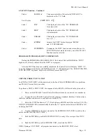
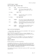
The NUMBER of TURNS is selected in MASTER MODE (see 3.2.2), through the use of the
SCALE function key. The selected TURNS value is used by all four PROGRAMS.
Control Unit in Master Mode
Select:
SCALE
Display:
TURNS
1
0 0
(Highlighted character indicates blinking character that can be changed)
Select:
DATA 0 - 9
The numerical value of the DATA KEY (i.e. 0-9) is
Displayed in the cursor position of the TURNS field
to a maximum value of 100.


