PLS-601 User's Manual
Document #11696 Page - 6
3.2.2 PLS-601 FRONT PANEL USER INTERFACE - Continued
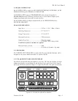
Each element of the front panel will be discussed in order to give insight into the operation of the
PLS-601 unit. The description of the front panel elements follows.
Display:
The PLS-601 front panel user interface is equipped with a 16 digit alphanumeric display
that is used to inspect and/or program data fields or operating modes of the unit. The display is of
the vacuum fluorescent type which provides bright, easy to see visual feedback even in dimly
lighted areas.
Mode Keyswitch:
The mode keyswitch protects the user program data from being changed by
unauthorized personnel, through the provision of three, key-selectable modes of operation. In
Display mode, program data can be displayed and verified, but not changed. In Program mode, all
standard PLS-601 functions can are enabled, allowing the user to enter program data into memory
even while the unit is operating. In Master mode, access is allowed to a set of optional Master
functions that are normally required only during system installation and configuration. The key
can only be removed while the switch is in the display mode position.
Function/Data Keys:
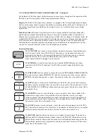
The
FUNCTION
key is used to select whether the ten dual-purpose function/data keys
are to be used to select one of the PLS-601 functions, or to enter numerical data. By
pressing the function key, the associated function LED will either turn on to indicate
function entry mode, or turn off to indicate data entry mode. While in data
mode, numerical data 0 through 9 can be entered.
The
ENTER
key is used to enter data into non-volatile EEPROM memory during
execution of the PLS-601 functions. The PLS-601 currently supports the following
functions:
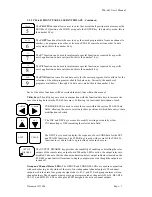
The
POS/TACH
function is used to display the selected PROGRAM NUMBER (PROG),
the current resolver angle POSITION (P), and the current speed of the resolver shaft in
RPM (R) when the function key is active. In data entry mode, this is the number 0 key.
The
SET
function is used to enter LOBE data in to the PLS-601 control unit's memory.
Set allows single or multiple lobes to be entered on any or all of the 64 channels. A total
of 3808 LOBES (238 LOBES per channel group per program). In data entry mode, this is
the number 1 key.
The
OFFSET
function is used to display or enter a positive value that is added to the
actual resolver angle value. This parameter is used to align the resolver zero angle
reference point to the actual machine zero angle reference point. In brief, electrical zero
can be adjusted to match that of mechanical zero through the use of the OFFSET value.
In data entry mode, this is the number 2 key.
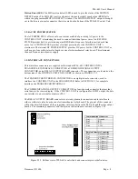
The
SCALE
function is used to display or enter the scale factor parameter into the PLS-
601 Control Unit's memory. The scale factor is the number of intervals that one complete
resolver rotation is divided into. In data entry mode, this is the number 3 key.
The
MOTION
function allows the user to set a window for shaft speed. If the resolver
shaft speed falls within the defined window criteria, the MD LED (Motion Detect) and
Motion Detect outputs will provide visual and electrical feedback depending on how the
Motion Detect parameters are programmed into the control unit's memory. In data entry
mode, this is the number 4 key.
FUNCTION
ENTER
POS/TACH
0
SET
1
OFFSET
2
SCALE
3
MOTION
4


