8(12)
Central unit:
(art. no. 2220092)
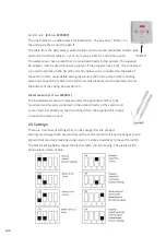
The sink cabinet is a suitable place for installation. The box has a "button" on
the underside that is used to open it.
The cable from the ball valves is pulled to the central unit and connected to the 2-pole
terminal V3 with red cable to +. (For more valves, both V1 and V2 are used.)
The water sensor has a socket that is connected directly to the outside. The supplied
DC adapter must be used for power supply or if the property has 12 vdc, it is connected
via a terminal block on the circuit board. All cables can be connected on the back of
the central unit to avoid visible wiring, disconnect the centre plate on the mounting
plate and connect the cables to the terminals. Alternatively, use the premade hole at
the bottom of the casing. See section 2.5.
Water sensors: (art. no. 2230011)
The included water sensor is placed under the appliance which is to be
monitored and is easily connected to the socket directly in the central unit
or via a terminal directly on the circuit board. Use the supplied Velcro tape
to mount the water sensor.
2.3 Settings:
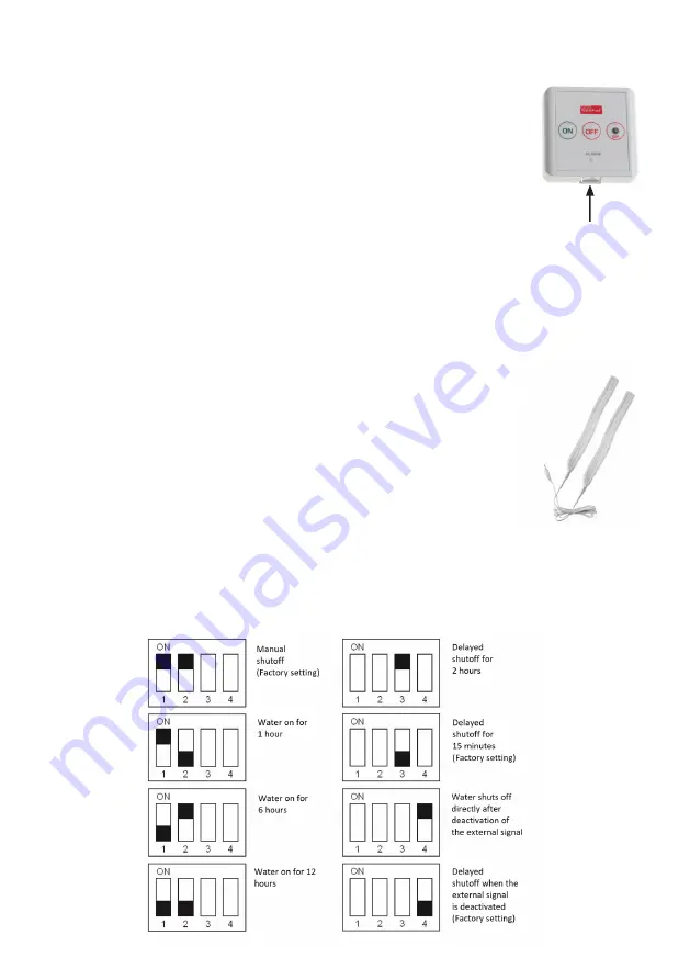
There are a number of settings that can be changed for the product.
Settings are changed with dip switches on the central unit circuit board. Changes to the
dip switches are easily made by using a pen or a small screwdriver to move the switch.
The black marking below shows the plastic switch you are moving. The plastic switch
can be black, white, or blue.
"Button"


