15
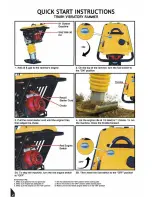
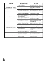
4.4 To Start
1. Add 91 Octane Gasoline and SAE10W30 Oil to the engine.
2. Set the engine ON/OFF switch to the “ON” position.
3. On the top of the rammer, turn the fuel switch to the “ON” position.
4. Grip the recoil starter handle and pull it until you feel slight resistance. Then pull sharply
and quickly. Return the recoil starter handle to the starter case before releasing.
5. If the engine has started, warm-up the engine for a period 3 to 5 minutes at low speed,
while paying careful attention.
NOTE: If it is difficult to start the engine by repeatedly pulling the starter rope, remove
ignition plug and check the sparking performance. If the plug is wet due to excessive fuel
intake or soiled, replace the coil or clean sufficiently. With the ignition plug removed, pull
the recoil starter handle 2-3 times to discharge excessive gas.
4.5 Operation
1. Turn the choke lever to open the choke. Run the engine for 5 minutes at low speed to
warm the engine.
2. Move the throttle lever quickly to the “FULL OPEN” position. DO NOT move the throttle
lever slowly as this may cause damage to the clutch or spring.
3. After starting the tamping action, adjust the jumping motion to suit the particular soil
condition by lightly controlling the throttle lever. When the engine speed falls between the
set values shown on the engine, your work can be carried out at the best efficiency. Increas
-
ing the engine speed unnecessarily does not cause the compaction force to increase. On
the contrary, a resultant resonance causes the compaction force to decrease, damaging the
machine.
4. Under cold weather, the oil in the machine may become viscous, causing the tamping
rammer to perform somewhat irregular movement. It is recommended to perform a
warm-up run while moving the throttle lever repeatedly between ON and OFF positions,
before beginning to work.
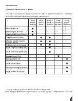
Make sure that the throttle lever is moved to the FULL OPEN position.
Operating the rammer at less than full speeds can result in damage to the
clutch springs or foot.
WARNING
Summary of Contents for TR68H
Page 2: ...2 ...
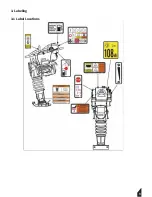
Page 9: ...9 3 Labeling 3 1 Label Locations ...
Page 13: ...13 ...
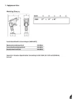
Page 23: ...7 Equipment Size 23 ...
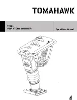
Page 29: ...TR68H VIBRATORY RAMMER Operations Manual 29 ...
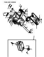
Page 30: ... TANK AND HANDLE 17 ...
Page 32: ... CRANK CASE ASSEMBLY ...


