background image


TOMARK, s.r.o. 


 Airplane Maintenance Manual 

Chapter 91 Charts 

Issue: 28.FEB 2017 

Page 199 


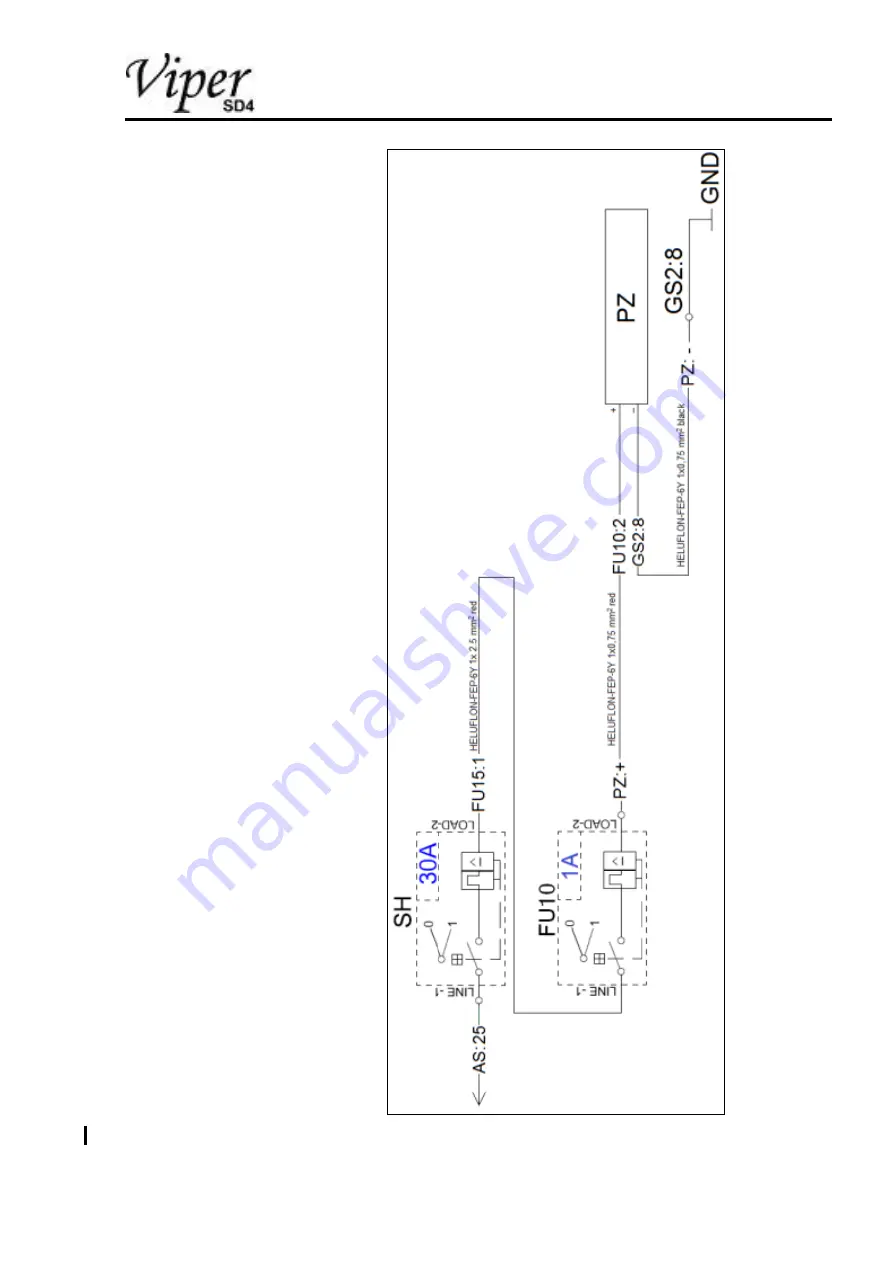
Figure 49 

FU10 power supply for Socket 12/1A 

Summary of Contents for Viper SD-4 RTC

Page 1: ...TOMARK s r o Airplane Maintenance Manual Issue 04 APR 2016 Page 1 00 Preceding Pages Viper SD 4 RTC Airplane Maintenance Manual Doc N TOM TC 01 AMM ...

Page 2: ...TOMARK s r o Airplane Maintenance Manual Chapter00 Preceding Pages Page 2 Issue 11 AUG 2016 Intentionally left blank Issue 04 APR 2016 ...

Page 3: ...issue Revision 1 11 AUG 2016 3 5 7 17 24 29 58 66 200 Chapter 05 50 02 and 51 60 added editorial changes Revision 2 15 FEB 2017 3 104 109 187 190 AD C DC 58 003 Dual trim design change Revision 3 28 FEB 2017 3 5 10 15 31 132 203 AD C DC 58 004 Landing Light Revision 4 25 APR 2017 3 5 33 56 Exhaust silencer Standard Major Change EASA Project No 0010045844 Issue 25 APR 2017 ...

Page 4: ...TOMARK s r o Airplane Maintenance Manual Chapter00 Preceding Pages Page 4 Issue 11 AUG 2016 List of Service Bulletins SB No Date Title Affected Serial no s AD EASA Issue 04 APR 2016 ...

Page 5: ... FEB 2017 6 04 APR 2016 7 9 11 AUG 2016 10 15 28 FEB 2017 16 17 11 AUG 2016 18 23 04 APR 2016 24 11 AUG 2016 25 28 04 APR 2016 29 11 AUG 2016 30 04 APR 2016 31 28 FEB 2017 32 57 04 APR 2016 33 25 APR 2017 56 25 APR 2017 58 11 AUG 2016 59 65 04 APR 2016 66 103 11 AUG 2016 104 15 FEB 2017 105 108 11 AUG 2016 109 15 FEB 2017 110 131 11 AUG 2016 132 203 28 FEB 2017 Issue 25 APR 2017 ...

Page 6: ...uidelines 16 01 30 Related Publications 17 01 40 Addresses 18 02 How to Use the Manual 19 02 00 General 19 02 10 Notes 20 02 20 Terminology and Abbreviations 21 02 30 Standard Elements 21 02 40 Safety 22 03 General Description 23 03 00 General 23 04 Limitations 24 04 00 General 24 04 10 Structural Limitations and Inspection Intervals 24 04 20 Placards 25 04 30 Major Inspection 25 04 30 10 Major In...

Page 7: ...ck Flight 57 05 21 10 Performance Tests 58 05 21 20 System Tests 59 05 21 21 Flight Controls 59 05 21 22 Engine Controls 60 05 21 23 Other Controls 60 05 21 24 Flight Instruments 61 05 21 25 Avionics 61 05 21 26 System 62 05 21 27 Engine Monitoring System EMS 63 05 21 28 Other Instruments 64 05 21 30 Flight Handling Tests 65 05 50 Unscheduled Maintenance 66 05 50 01 Inspection after Spin Event 66 ...

Page 8: ...ting a Main Wheel 73 07 00 02 Lifting the Nose Wheel 74 07 10 Jacking 75 07 10 01 Jacking the Aircraft Side 75 07 10 02 Jacking the Aircraft Front 76 08 Leveling Weighing 77 08 10 Weighing and Balancing 77 08 20 Leveling 81 12 Servicing 82 12 10 Replenishing 82 12 10 01 Refueling Defueling 82 12 10 02 Oil Change 82 12 10 03 Coolant Replacement 83 12 10 04 Brake Fluid Bleeding 83 12 10 05 Brake Flu...

Page 9: ... 24 60 10 Electric Current Protection 95 25 Equipment and Furnishings 96 25 10 Flight Compartment 96 25 10 01 Seats 96 25 10 02 Seat Belts 96 25 10 03 Paneling 96 25 50 Baggage Compartment 97 27 Flight Controls 98 27 00 01 Control Stick 100 27 00 02 Control Rod 100 27 00 03 Bell Crank 100 27 00 04 Bracket 101 27 10 Aileron Control 102 27 10 01 Aileron 103 27 10 02 Aileron Trim 104 27 20 Rudder Con...

Page 10: ... breakers 120 32 Landing Gear 121 32 10 Main Gear 122 32 10 01 Main Gear Leg 122 32 20 Nose Gear 123 32 20 01 Nose Gear Strut Fairing 123 32 20 02 Nose Wheel Fairing 123 32 20 03 Wheel Fork 123 32 20 04 Shock Cord Ring 124 32 20 05 Steel Cable Deflection Limiter 127 32 40 Wheels and Brakes 127 32 40 01 Main Wheel Fairing 127 32 40 02 Main Wheel 128 32 40 03 Brake Cylinder 129 32 40 04 Brake 129 32...

Page 11: ...6 51 71 03 Stopping Cracks 147 51 71 04 Repairing the Skins with Patches 147 51 71 10 Repair of U Profile 151 51 72 Repair of Composite Parts 151 51 72 00 Parts of External Appearance 152 51 72 01 Small damage 152 51 72 02 Medium Damage 154 51 72 02 Major damage 156 51 72 10 Structural Parts 156 51 72 11 Small Damage 156 51 73 Repair of Paint 157 51 73 01 Small Damage 161 53 Fuselage 163 53 00 01 ...

Page 12: ...61 Propeller 171 61 10 01 Propeller Blade 171 61 10 02 Spinner 171 71 Power Plant 172 71 00 01 Top Engine Cowling 172 71 00 02 Bottom Engine Cowling 172 71 60 Air Intakes 173 72 Engine 174 72 20 Inlet Section 174 72 20 01 Carburetor Preheating 174 73 Engine Fuel and Control 175 73 20 Controlling 175 73 20 01 Throttle Lever 175 73 20 02 Choke Control Knob 175 74 Ignition 176 75 Air 177 75 20 Engine...

Page 13: ... 179 79 10 01 Oil Tank 179 79 20 Distribution 179 79 20 01 Oil Gear Pump 179 79 20 02 Oil Radiator 180 79 20 03 Oil Filter 180 79 20 04 Oil System Ventilation 180 79 20 05 Oil Temperature Sensor 180 79 20 06 Oil Thermostat 180 80 Starting 181 80 00 01 Starter 181 90 Emergency Equipment 182 90 10 Aircraft Emergency Parachute System AEPS 182 91 Charts 186 Issue 28 FEB 2017 ...

Page 14: ...ent panel 117 Figure 18 Landing gear 121 Figure 19 Shock cord ring replacement 125 Figure 20 Position light removal installation 133 Figure 21 Landinglight removal installation 134 Figure 22 Zip tie holder 134 Figure 23 Access hatches covers and fairings 136 Figure 24 Rudder balancing 141 Figure 25 Elevator balancing 141 Figure 26 Aileron balancing 142 Figure 27 Flap balancing 142 Figure 28 Locati...

Page 15: ... 192 Figure 43 FU15 power supply for intercom 193 Figure 44 FU7 power supply for Radio 194 Figure 45 FU1 FU9 power supply for EFIS display and transponder 195 Figure 46 FU5 power supply for Flaps 196 Figure 47 FU8 power supply for GPS 197 Figure 48 FUL FU6 power supply for Strobo lights and Nav lights 198 Figure 49 FU10 power supply for Socket 12 1A 199 Figure 50 FU4 power supply for Starter Power...

Page 16: ...quately qualified licensed personnel in accordance with the applicable continued airworthiness regulations For any maintenance or repair activity not addressed in this manual contact TOMARK s r o for approved instructions The instructions for installation service repair and maintenance of optional equipment shall be collected with this Manual 01 10 Coverage This manual provides servicing and maint...

Page 17: ... Authority ROTAX AIRCRAFT ENGINES Maintenance Manual Line Maintenance for ROTAX Engine Type 912 Series Edition 3 Rev 2 February 01 2015 or later revisions only if agreed for use by TOMARK1 Operators Manual for ROTAX Engine Type 912 Series Edition 3 Rev 2 February 01 2015 or later revisions only if agreed for use by TOMARK1 http www flyrotax com NEUFORM COMPOSITE PROPELLERS Operating Manual NEUFORM...

Page 18: ...pter01 Introduction Page 18 Issue 04 APR 2016 01 40 Addresses Contact Company Address TOMARK s r o TOMARK s r o Aero division Strojnícka č 5 080 01 Prešov Slovak republic sales tomarkaero com ROTAX AIRCRAFT ENGINES Refer to Rotax Service network ...

Page 19: ...l information Aircraft 03 thru 20 Complete operational unit limitations Airframe systems 24 thru 34 All airframe systems except power plant Structures 51 thru 57 All aircraft main structures Propeller 61 Propeller information Power Plant 71 thru 80 Power plant information Miscellaneous 90 91 Emergency equipment Charts Supplementary information To be collected in Appendix Forms Advanced maintenance...

Page 20: ... the words NOTE NOTICE CAUTION WARNING or DANGER in the left margin column The text of the note or safety note is printed in bold See the following definitions DANGER indicates a hazardous situation which if not avoided will result in death or serious injury WARNING indicates a hazardous situation which if not avoided could result in death or serious injury CAUTION indicates a hazardous situation ...

Page 21: ...Air Traffic Control CG Center of gravity EFIS Electronic Flight Instrument System EGT Exhaust Gas Temperature EMS Engine Monitoring System LH Left Hand LSA Light Sport Aircraft MFD Multifunction Display RH Right Hand TC Type Certificate 02 30 Standard Elements Text Elements The following text elements are generally used within this manual Normal text Itemization Instructions Instructions within a ...

Page 22: ...al and related instructions Wear ventilated protective clothing protective goggles chemical resistant gloves and respiratory mask when working with solvents or in dusty conditions Use protective goggles in particular when machining some metal and laminate parts Wear safety gloves to protect yourself against high temperatures Observe and follow the instructions of related products data and safety s...

Page 23: ...ion Issue 04 APR 2016 Page 23 03 General Description 03 00 General The Viper SD 4 RTC is a low wing aerodynamically controlled single engine two seat with side by side configuration fixed tricycle landing gear with steerable nose wheel all metal airplane Figure 1 View ...

Page 24: ...craft Other airworthiness limitations such as operational limitations e g speeds temperatures pressures fuel and oil grades required placards etc are given in the approved airplane flight manual TOM TC 01 AFM For further manufacturer recommended time limits maintenance checks and inspections refer to Chapter 05 Time limits Maintenance checks The aircraft must be released to service by certifying s...

Page 25: ...t Relevant P N Wing main spar SD4 A 2 021 N 1 Wing aft spar SD4 A 2 222 P 3 SD4 A 2 223 N 3 Main fuselage cross beam SD4 A 1 075 N 1 Aft fuselage cross beam SD4 A 1 236 N 3 Aft spar attachment SD4 A 1 294 L 7 SD4 A 1 295 L 7 SD4 A 1 295 P 7 SD4 A 1 294 P 7 SD4 A 1 244 N 3 Horizontal stabilizer spar SD4 A 3 031 N 3 Horizontal stabilizer interface SD4 A 1 156 N 3 SD4 A 1 157 N 3 Elevator torsion bra...

Page 26: ...ss using appropriate straight ruler lengths Check torque of all attachment bolts At locations where bolt torque is below the specified values remove bolt and inspect for sights of wear or overload Discharge the respective stop nuts If a bent bolt is found the engine mount must be removed from the airframe to further inspect the respective bearings on airframe and engine mount side Report such cond...

Page 27: ...identified scratches Reinstall engine if removed Make appropriate airplane log book entry for release to further service 04 40 Software Only Software delivered with the airplane or as mandated by respective Service Bulletins are approved to be used in the Viper SD 4 RTC This addresses Function Unit Software revision approved at time of print MFD EMS configuration Dynon Skyview System SV D1000 vers...

Page 28: ...ional inspection or calibration items as well as replacement overhaul intervals not described in this manual It is the responsibility of the operator and maintenance personnel to adhere to national regulations 05 10 Time Limits and Inspection Program The Viper SD 4 RTC aircraft scheduled inspection and maintenance program comprises Non repetitive aircraft inspection at 25 hours after delivery of t...

Page 29: ...etrant inspections at the welding connections and highly stressed areas as indicated in the inspection list 05 10 01 Component Time Limits Time Between Overhaul Component Interval Propeller Neuform 1500 h Rotax 912 S ULS Engine 2000 h 15 years refer to latest ROTAX documentation applicable to the actual SN of the engine Time Between Replacement Component Interval ELT Batteries 5 years Dynon SkyVie...

Page 30: ...ctivities Review of aircraft logbook 1 Carry out a Daily Inspection according the flight manual 1 Flight check according to 05 21 Maintenance Check Flight review results 1 Start up engine in accordance with AFM 1 Check all engine related instrumentation and fuel quantity 1 Check voltage indication 1 Check function of exterior lights as installed 1 Shut down in accordance with AFM 1 Check that all ...

Page 31: ...wling internal coating for deterioration and signs of overheat 1 Inspect Landing Light attachment 1 Inspect Landing Light wiring attachment 1 Engine Installation Take precautions against accidental starting or firing of the engine by removing ignition leads 1 Perform engine inspection oil change etc according to ROTAX 912 Line Maintenance and Operators Manual Chapter 05 20 00 1 Air Induction Visua...

Page 32: ...their fittings and the tightness of the oil system If necessary tighten the hose connection fittings or replace damaged hoses 1 Visually check the condition and attachment of the oil tank Visually check the condition attachment and tightness of the oil radiator Coolant System Visually check the condition of the radiator mounting brackets for cracks 1 Check coolant thermostat for proper attachment ...

Page 33: ...e due to vibration and thermal expansion 1 Check EGT sensors for proper installation 1 Visually inspect muffler and additional muffler for cracks leakage and security of attachment 1 Engine Controls Check throttle control for proper attachment full travel freedom and smoothness of movement 1 Clean and lubricate Bowden cable Refer to Luprication plan 500h 5 Years Inspect all wiring connected to the...

Page 34: ...unt rubber elements vibration isolators for condition 1 Check engine to shock mount attaching bolts castle nuts and cotter pins 1 Inspect engine mount structure for cracks and damage Pay specific attention to weld connections In case of doubt consider dye penetrant inspection Visually check the firewall for cracks and corrosion in particular in the places of all the engine mount attachment points ...

Page 35: ...inate the gear influence Measure actual propeller blade angles 22 0 5 at 425 mm from root of the blade gaugeable secant angle Reinstall spinner Check for proper attachment 1 Finish Inspect entire engine compartment for foreign objects loose connections of earlier work correct application of safety wire and cotter pins at all locations where work was executed 1 Landing Gear Brakes Nose Landing Gear...

Page 36: ...for deformation cracks in welding seams or due to material fatigue or stress Check the condition of the static discharge wire Nose Landing Gear Wheels and Tires Check the attachment of the wheel disk and its locking Inspect tires for cracks cuts and condition Check the condition of the valve at the opening of the rim Inspect slip marks for proper alignment Visually check the wheel disk for cracks ...

Page 37: ...damage Inspect tires for cracks cuts and condition Check the attachment of the wheel disks and their locking Visually check the wheel disks for cracks and deformities Check the condition of the valve at the opening of the rim Inspect slip marks for proper alignment Check the play in the bearings and the free turning of the wheels Brakes Inspect brake cylinder in the cockpit for leakage damage and ...

Page 38: ...d Check the condition and attachment of the wing tip and navigation lights Inspect wing internal for accumulation of water and or moisture Demount the inspection hatches and check the condition of the control pull push rods Check for torque of joints jamming excessive play and excessive wear Correct on condition Visually check the condition of the rivet joints and sealant of the fuel tanks for tig...

Page 39: ...rim servo and the locking of the trim tab control push pull rod Check the electric cables of the trim tab control for damage Check the piano hinges attachment of the ailerons for play and other damage Flaps Completely extend the flaps and visually check the overall condition of the skin and riveting Check the flap attachment hinges Check the play of the flaps Check the torque and locking of the fl...

Page 40: ...rding to the lubrication plan Section 05 20 02 Lubrication Chart Reinstall the wing root fairings only after the completion of the inspection Fuselage Visually check the skin and the riveting No deformities cracks or loosened rivets are allowed Visually check the rivets near the main landing gear legs Check the condition and the attachment of the antennas beacons and other external installations P...

Page 41: ... attachment of the stabilizer tip fairing Check the attachment of the horizontal stabiliser by moving the stabiliser forward and backward up and down Check the attachment elements of the stabiliser the torque and locking of the bolts Elevator Visually check the condition skin and riveting of the elevator Deformations cracks scratches and loosened rivets are not allowed Pay specific attention to we...

Page 42: ...inges Check the elements of the attachment of the vertical stabiliser the torque and locking of the connecting elements Check for other possible damage Rudder Visually check the condition of the rudder check the hinges Deformations cracks scratches and loosened rivets are not allowed Visually check the hinge for corrosion the torque and locking of the pins and connections of the rudder control Lub...

Page 43: ...ened rivets and other damage are not allowed Pay specific attention to wing spar attachment areas Control systems Flap Actuation System Check for condition and proper smooth operation through full travel Check for free movement Lubricate bearings as required 05 20 02 Lubrication Chart Visually check the attachment torque and locking of the electric flap drive in fuselage Check condition of the fla...

Page 44: ...tructure Check condition and security of travel stops Replace aileron travel stop Teflon strips on condition Check push rods inside the wing for condition and security Visually check control stick weld seams and for tube deformation 500h 5 years Check aileron deflections Nominal values Up 27 1 Down 16 1 500h 5 years Check elevator deflections Nominal values Up 25 1 Down 20 1 500h 5 years Elevator ...

Page 45: ...heck rudder pedals for general condition and proper attachment Visually inspect for cracks and deformation Check rudder deflections Nominal values Left 30 1 Right 30 1 500h 5 years Fuel System excluding firewall forward Turn on the fuel pump do not start the engine Open shut off valve and check all fuel system connections downstream of the electric fuel pump for leaks 200h 2 Years Check fuel press...

Page 46: ... in system is below published unusable quantity of 5 Liter per side Low level warning must trigger at steady quantity of 10 Liter per side 500h 5 years Instruments Check instruments for condition security and proper markings Instrument dials or markings may not be excessively faded out due to sunlight Check instrument lines and wiring for condition proper routing and security Check Pitot static sy...

Page 47: ... Guide latest Revision 1 Follow the Instructions of Continued Airworthiness as per DYNON AVIONICS SkyView System Installation Guide latest Revision Check ELT for condition and exp Date of battery replace battery if needed Perform radio and transponder check 1 Magnetic Compass Check magnetic compass for security and cleanliness Inspect for leakage and evidence of damage Perform magnetic compass com...

Page 48: ...Aerodynamic fairings Note If specific work involved opening closing of oil coolant or fuel system related hose connections it is advised to execute a short ground run without cowling to check for leaks 2 Check seat belt routing 2 Check control system operation 2 Reattach ignition leads to spark plugs if removed Reattach air box hose if bottom cowling was removed 2 Ground Run Perform engine ground ...

Page 49: ...ice 1 Ensure all Maintenance Record log book entry s required are complied with before the aircraft return to service 1 File all documents e g inspection report ground run report Forms and tags in aircraft history file 1 05 20 02 Lubrication Chart Three types of lubricants are used which are recommended LPS1 Non fat lubricant Basic characteristics dissolve fat and oils repels oil dust and sediment...

Page 50: ...ssed bearings Temperature range from 30 C to 150 C appropriate for bearings joint mechanisms and reduction devices expand lifetime of lubricate mechanism excellent corrosion protection non soluble in water easy to use NOTE Flight plastic lubricant AeroShell Grease 22 can be used as an acceptable alternative for Castrol LMX Item Lubricant 100 h as specified Engine Throttle control cable spring 2x L...

Page 51: ...ar Upper and lower plastic slide bearing Castrol LMX Arresting plastic washers 2x 1 Front rods nodes 2 nodes Flaps Wings flaps controls Flaps 2x 2 nodes Castrol LMX 500 h Flaps hinges 2x 3 nodes Ailerons Wings ailerons controls 2x 7 nodes Castrol LMX 500 h Ailerons Trim piano hinge 3x hinge LPS1 1 First 25 hours of operation for new or overhauled engine ...

Page 52: ...age 52 Issue 04 APR 2016 Item Lubricant 100 h as specified Rudder Rudder hinges 2 nodes Castrol LMX Rudder lever control 2 nodes 500 h Bowden wire on the outlet 2x LPS2 Elevator Elevator hinges 4 nodes Castrol LMX Elevator lever 2 nodes LPS2 Elevator trim piano hinge 1x hinge LPS1 ...

Page 53: ...des Castrol LMX 500 h Rods and lever elevator control 4 nodes 500 h Servo flap joint mechanism 1 nodes 500 h Lever joints of aileron control 2 nodes LPS2 500 h Rudder control Guidance slots in steering lever 2 nodes Castrol LMX Connection place of nose landing gear rods and levers 2 nodes 500 h Levers joint mechanism 2 nodes Connection nodes of rudder Bowdens 2 nodes 500 h Rudder Bowden wire 2x LP...

Page 54: ...enance Page 54 Issue 04 APR 2016 Item Lubricant 100 h as specified Cockpit Rotary joints of cockpit arm dumper 2x 2 nodes LPS2 500 h Hinge bearings of cab canopy 2 nods 500 h Slide plastic bearing cab lock 2 nods 500 h Lock bearings and cab arms 2x 2nods Castrol LMX 500 h ...

Page 55: ... Airplane Maintenance Manual Chapter05 Inspection and Maintenance Issue 04 APR 2016 Page 55 Item Lubricant 100 h as specified Throttle Connecting areas of sliding bearing 500 h Throttle control cable 2 cables 500 h ...

Page 56: ... status just clean and inspect In case the bearing shows signs of wear they need to be replaced The wheel bearings are life time lubricated in case of questionable status they need to be replaced 05 20 03 Drain Holes Drain holes are located in fuselage and empennage bottom and one drain hole is located at the bottom of additional exhaust muffler Drain holes must be inspected regular for obstructio...

Page 57: ...ave not been discovered in prior inspections The Maintenance check flight is to be conducted using the Maintenance Check Flight Form Figure 53 On this form all the items to be checked are indicated For all the relevant items a short description is given here The maintenance check flight is not intended to fly a complete evaluation program but covers all the relevant items satisfactorily to be able...

Page 58: ...e monitored Climb Fly the aircraft at a speed 65 KIAS using a full throttle and flaps retraced Fly this as stationary as possible while monitoring the flight and engine instruments Note down the relevant values on the form Do not fly this test for a too short period Allow the engine to stabilize the oil temperature Compare this data with the data displayed in the airplane flight manual The correct...

Page 59: ...the form indicate an acceptable functionality with a A functionality which is not acceptable should be indicated with a Use the reverse of the form to write down possible comments or complaints Try to be as accurate as possible in writing the comments complaints This will allow maintenance personnel to handle this adequately 05 21 21 Flight Controls Elevator Aileron Rudder Flap Check the elevator ...

Page 60: ... less than VF 79 KIAS Select intermediate flap position then full flap position verifying visually that the flaps have deployed and retracted correctly 05 21 22 Engine Controls Throttle Check the smooth operation of the throttle over its complete range check friction lock function The engine should give a direct response Engine Electric Control Switches Check the operation of the engine key switch...

Page 61: ...c compass turning errors in tuning or accelerating flight Airspeed Altitude Indication Check the logic and smooth functioning of the pitot static related indicators While increasing speed do not allow the speed to increase above VNE While decreasing speed do not stall the aircraft Indicated situation should follow actual situation instantaneous Lagging or sticking indication is reason for complain...

Page 62: ...le to see the effects from both left and right bank on the instrument Furthermore check the functioning of the slip indicator Slipping the aircraft both to the left and to the right should result in a logical indication Check accuracy of the instrument by timing a full 360 turn GPS Check the functionality of the GPS See whether the reception of satellite signals is sufficient Furthermore check the...

Page 63: ...compass while executing turns Airspeed Indicator Altimeter Variometer Check agreement of SkyView airspeed and altitude readings with those of the analog instruments Accelerometer Select the g meter display and verify the indication to correlate with bank angle in turning flight There is no need to deliberately attempt more than 2g equivalent to coordinated turn with 60 bank and constant speed Skyv...

Page 64: ...tle setting In idle conditions the CHT of the various cylinders will have a higher spread in stabilized conditions above 4000RPM the difference between the two EGT signals should be no more than 20 C 05 21 28 Other Instruments Fuel Quantity Indicator Check the functioning of the fuel quantity indicator by monitoring the indication during the flight During the flight the indication should become le...

Page 65: ...ned on the type in previous flights He should base his judgment on all items tested so far in the maintenance check flight He should address flight handling the possibility to trim the aircraft and the control authority High Speed In this part of the test the pilot should fly speeds up to VNE This speed should be approached carefully with sufficient altitude left for recovery since this speed will...

Page 66: ...rmed as a pilot owner inspection Refer to COMMISSION REGULATION EC No 2042 2003 M A 803 Pilot owner authorization Inspection after Spin Event Check play in flap system check in all flap positions and on both sides of the aircraft No excessive play allowed max 3 mm movement of flap trailing edge Unmount LH and RH seat Inspect rivet connections of torsion tube close to RH and LH fuselage sidewall us...

Page 67: ...zontal surfaces 1 AL distance between measuring points 6 3 1345 mm 3mm 2 AR distance between measuring points 6 3 1345 mm 3mm 3 BL distance between measuring points 6 9 1900 mm 3mm 4 BR distance between measuring points 6 9 1900 mm 3mm 5 CL distance between measuring points 7 8 1337 mm 3mm 6 CR distance between measuring points 7 8 1337 mm 3mm 7 DL distance between measuring points 6 2 2467 mm 5mm...

Page 68: ...TOMARK s r o Airplane Maintenance Manual Chapter05 Inspection and Maintenance Page 68 Issue 04 APR 2016 Figure 3 Measuring Sections Issue 11 AUG 2016 ...

Page 69: ...TOMARK s r o Airplane Maintenance Manual Chapter05 Inspection and Maintenance Issue 04 APR 2016 Page 69 Figure 4 Measuring Points Identification Issue 11 AUG 2016 ...

Page 70: ...efined by the horizontal orientation of the canopy frame 06 10 Main Data 06 10 01 External Dimensions Length 6 400 m Height 2 200 m Wing span 8 340 m 06 10 02 Wing Area 10 450 m2 Wing chord 1 290 m Aspect ratio 6 6 Wing profile NACA 4415 Wing platform rectangular Incidence angle 3 Dihedral 3 Sweep angle 0 Wing twist 0 06 10 03 Aileron Area each 0 260 m2 Span each 0 960 m Chord 0 270 m ...

Page 71: ... each 0 560 m2 Span each 2 197 m Depth 0 255 m 06 10 06 Horizontal Tail Area 2 220 m2 Span 2 800 m Chord 0 785 m Platform rectangular Profile NACA 0010 Incidence angle 1 5 Dihedral 0 Leading edge sweep angle 0 Twist 0 06 10 07 Elevator Area 0 750 m2 Span 2 600 m Chord 0 320 m 06 10 08 Elevator Trim Tab Span 928 mm Chord 86 mm 06 10 09 Vertical Tail Area 1 178 m Height 1 300 m ...

Page 72: ...e Profile NACA 0010 06 10 10 Rudder Area 0 560 m Leading edge sweep angle 35 Trailing edge sweep angle 11 06 10 11 Fuel System Fuel tank capacity 2 x 50 litres 06 10 12 Landing Gear Track width 2 190 m Wheel base 1 270 m Main wheels 4 00 6 Kašpar K 226A 000 6 Nose wheel 4 00 6 Kašpar K 116A 000 6 06 10 13 Propeller Number of blades 3 Diameter 1 650 m ...

Page 73: ...other 07 00 01 Lifting a Main Wheel Generally work with to persons lifting a wing Apply parking brake NOTICE Damage to the wing surface possible Do not push on unsupported surface areas Always place hands next to the wing main spar and the ribs Lift the main wheel by pushing up the applicable wing side by hand in areas as shown in the following figure If applicable place the wheel on a scale or ja...

Page 74: ...horizontal stabilizer surface possible Do not push on unsupported surface areas Always place hands next to the horizontal stabilizer main spar and the ribs Lower the aircraft tail as far as necessary by pushing down the horizontal stabilizer by hand in areas as marked Place the nose wheel on scale or jack aircraft front as per Chapter 07 10 02 Jacking the Aircraft Front ...

Page 75: ...d Shoring Issue 11 AUG 2016 Page 75 07 10 Jacking 07 10 01 Jacking the Aircraft Side Ensure parking brake is applied Lift applicable wheel Place a cushioned jack in the marked area 1 under the fuselage as shown in the following figure opposite side symmetrically ...

Page 76: ... Chapter 07 Lifting and Shoring Page 76 Issue 11 AUG 2016 07 10 02 Jacking the Aircraft Front Ensure parking brake is applied Lift the nose wheel Place a cushioned jack in the marked area 1 under the fuselage as shown in the following figure ...

Page 77: ...plane mR weight on the right wheel of the main landing gear mL weight on the left wheel of the main landing gear mF weight on the wheel of the front landing gear mT total weight of the airplane equal to mR mL mF xT distance of the CG from the leading edge T centre of gravity LF distance of the front landing gear wheel axis from the wing s leading edge LM distance of the main landing gear wheel axi...

Page 78: ... calculation of the CG position it is necessary to know the length of the mean aerodynamic chord MAC The calculated CG position must be within the range specified by the manufacturer MAC 1 29 m Design limit of operational CG range 24 32 MAC Weighing Procedure When establishing the CG position and the subsequent calculation of the CG position as MAC proceed as follows NOTE Weigh the aircraft only o...

Page 79: ...Put 2 7 5 kg weights into the luggage compartments Fill the tanks with the minimum allowed take off fuel quantity for a 30 minute flight Load both seats with the maximum allowed crew weight that will cause the airplane to reach its MTOM of 600 kg The weighting procedure is the same as in the case of establishing of the front most CG position The calculation procedure is the same as in front most C...

Page 80: ...TOMARK s r o Airplane Maintenance Manual Chapter08 Leveling Weighing Page 80 Issue 11 AUG 2016 Weighing Record Signature Note CG positions Empty Weight Date ...

Page 81: ... leveling is the straight part of the canopy frame The identical distances of wing tips to an even floor are the reference for lateral leveling Place aircraft on an even floor Measure distances of wing tips to an even floor Align a spirit level towards the straight part of the canopy frame Place suitable wooden strips under the respective tires ...

Page 82: ... avoid excessive spillage due to thermal expansion If fuel is spilled ensure that the area of spillage is thoroughly flushed with water and that all residual fuel and vapour have dissipated or neutralized prior to starting the aircraft engine Refuel the aircraft by pumping or pouring fuel into the wing tanks through their filler caps Using appropriate containers defuel the aircraft by opening both...

Page 83: ...ted to the RH fitting and drain coolant Reinstall the hose The overflow bottle has to be drained and refilled separately CAUTION Burns possible due to hot coolant Allow coolant to cool down before working on the overflow bottle Place a suitable container under the overflow bottle Drain overflow bottle by disconnecting the coolant hose Connect the coolant hose Refill coolant 12 10 04 Brake Fluid Bl...

Page 84: ...with your skin In case of accidental contact flush with water immediately NOTICE Brake fluid can damage paint or other material Cover the affected areas with appropriate clothes or suitable containers Clean up immediately spilt brake fluid Brake fluid DOT3 HD 230 Liquid Standards ISO 4925 DOT3 SAEJ 1703F FM VSS 116 Carry out the following procedure generally with two persons One upper person sitti...

Page 85: ...he correct sequence brake valve first using a wrench and replenish brake fluid by pressing it from the bottom wheel to the top brake cylinder Watch the brake fluid spilling into the container If brake fluid is clear and free from air bubbles close the valves in the correct sequence brake cylinder valve first Repeat this procedure for the other wheel Lock brake lever in first position and thus keep...

Page 86: ...Bolted joints of Viper SD 4 RTC Can be downloaded from TOMARK website www vipersd4 com Mark the position of all bolted joints with red sealing varnish after locking 20 10 02 Rivets General Riveted parts are used in design of Viper SD 4 RTC airplane for whole fuselage wings flaps ailerons and tail unit In the following table there is a survey of rivets that are used on Viper SD 4 RTC airplane struc...

Page 87: ...EX series 1691 3 2x14 0 POP UP RIVET AVEX series 1691 4 0x8 0 POP UP RIVET AVEX series 1691 4 0x 9 5 POP UP RIVET AVEX series 1691 4 0x12 0 POP UP RIVET AVEX series 1691 4 0x12 7 POP UP RIVET AVEX series 1691 4 0x14 0 POP UP RIVET AVEX series 1691 4 0x16 7 POP UP RIVET AVEX series 1691 4 0x18 0 POP UP RIVET SR series 1201 3 2x6 5 POP UP RIVET SR series 1201 3 2x8 0 POP UP RIVET AVINOX II series BE...

Page 88: ...owing when riveting When drilling fix by clamps or clecos mutual position of assembled parts Holes of higher diameters pre drill with a drill bit of smaller diameter and then re drill them to the final size Fit the parts being connected and drill them together Hole diameter must be by 0 1 mm 0 004 in bigger than rivet shank diameter Disassemble the parts and deburr the holes NOTE Observe the follo...

Page 89: ...y means of the extrusion gun plastic spatula or paintbrush in such a way that the layer of sealant is equally thick and integral without bubbles or uncovered areas The optimum thickness of the applied coat is 0 25 mm 0 01 in After applying bonding sealant connect both parts together fix them by clecos and rivet them NOTE After proper riveting the continual bur of adhesive is created on the edge of...

Page 90: ...Bowden Cables Removal Note position of cable tie Remove cable tie Disconnect Bowden cable from actuator arm Remove firewall seal from firewall penetration Unscrew firewall penetration plastic grommet Loosen the counternut of control knob Pull out the Bowden cable Installation Install in reverse sequence of removal Seal firewall penetration with PR 812 sealant Check correct travel Adjust travel if ...

Page 91: ...d by plastic tubes to the air vents 2 above of the instrument panel and to two air nozzles 3 located on left and right instrument panels The air nozzles are controllable with ability to be closed by rotary motion Canopy glass ventilation is supplied by two canopy air inlets 4 The airflow is led to the air vents located on the front part of the cabin frame and is adjustable by valves 5 located at t...

Page 92: ...en cables two control knobs Fresh air is taken from the inlet located on the bottom of the lower engine cowling Through rubber hoses 3 the air is routed to the heat exchanger 5 at the exhaust muffler 4 and further to the selector boxes 2 The control valve is actuated via Bowden cable by the CABIN HEAT control knob located on the right side of the instrument panel From the control valve air is duct...

Page 93: ...K s r o Airplane Maintenance Manual Chapter 21 Air Conditioning Issue 11 AUG 2016 Page 93 Figure 6 Heating System Item Description 1 Firewall 2 Selector box 3 Rubber hoses 4 Exhaust muffler 5 Heat exchanger ...

Page 94: ... 30 DC Generation 24 30 10 Generator The electrical system is supplied by an in built AC generator with a rectifier 12 V 22 A DC This generator is part of the engine installation refer to Rotax documentation 24 30 20 Battery The battery VARTA 519901017 is an auxiliary source of electric energy located in the engine compartment on the left lower side of the firewall It is accessible after the remov...

Page 95: ...95 24 30 30 Signaling A regulator generator failure is signalled by a red warning light on the left hand side instrument panel 24 60 Distribution 24 60 10 Electric Current Protection The electric system consists of electric circuits protected by circuit breakers and the main 125 A melting fuse ...

Page 96: ...ct surface hook and loop fastener Remove the seats 4 Allen screws each Installation Install in reverse sequence of removal 25 10 02 Seat Belts Viper SD 4 RTC provides a SCHROTH 4 03 D802xx Type 3 point static harness restraint system The strap ends of the seat belts are attached to riveted brackets on the main fuselage spar The strap ends of the shoulder harnesses are attached to riveted brackets ...

Page 97: ...97 25 50 Baggage Compartment Baggage area is located in the cockpit right behind the pilot seats Area for baggage is divided into two storage parts and is integrated into the fuselage Both parts are covered by manually operated open close roller hard plastic blinds guided in rails over the full length ...

Page 98: ...nd the elevator The foot control pedals control the rudder and the front landing gear wheel The wing flaps are actuated electrically by a lever type controller Control Surface Deflections Aileron deflection angle up 27 1 down 16 1 Elevator deflection angle up 25 1 down 20 1 Flap deflection angle 0 2 15 2 30 2 40 1 2 Rudder deflection angle left 30 1 right 30 1 Elevator s trim tab deflection angle ...

Page 99: ...s r o Airplane Maintenance Manual Chapter 27 Flight Controls Issue 11 AUG 2016 Page 99 Figure 7 Control system Item Description Item Description 1 Rudder 4 Ailerons 2 Elevator 5 Control sticks 3 Flaps 6 Pedals ...

Page 100: ...ol Rod The control rods used in the Viper SD 4 RTC control system are equipped with two kinds of rod ends fork end ball bearing rod end The control rod attachment to the respective control levers and control surfaces is done generally with a typical castle nut bolt connection Removal Remove bonding lead if present from rod end 1 Allen screw with locking washer Note position of bolt side and washer...

Page 101: ... Chapter 27 00 02 Control Rod Note position of bolt side and washers Remove bell crank 1 bolt with castle nut and washers Installation Install in reverse sequence of removal 27 00 04 Bracket Brackets are used as a support for the control system bell cranks The brackets are attached to the aircraft structure by means of conventional rivet or bolt connections ...

Page 102: ...d to bell cranks The travel stops are located at the bottom of the control sticks under the seats Replace protective teflon tape on pushrods whenever rigging or unrigging of the control system Figure 8 Aileron control left side symmetrically Item Description Item Description 1 Aileron 4 Travel stops 2 Control rods 5 Control sticks 3 Bell cranks 6 Trim tab right side only ...

Page 103: ...pective aileron control rod Figure 9 Aileron Item Description Item Description 1 Right aileron 4 Trim motor support RH aileron only 2 Trim tab RH aileron only 5 Piano hinge 3 Crank arm Removal Remove win tip fairing as per Chapter 57 30 01Wing Tip Fairing Disconnect Control rod from aileron as per Chapter 27 00 02Control Rod Disconnect electrical wiring from trim tab RH aileron only Support the ai...

Page 104: ...Dynon Skyview instruments within the EMS panel 27 20 Rudder Control The rudder is controlled via a pair of control cables They are routed from the rudder pedal linkage through the center of the fuselage to the tail There they penetrate the left and right fuselage side walls and are connected to the rudder crank arms The rudder travel stops are located on the side of the fuselage tail next to the r...

Page 105: ...l Item Description Item Description 1 Rudder 4 Pedals 2 Rudder crank arm 5 Bellcrank 3 Bowden cable 27 20 01 Rudder The rudder is connected to the respective vertical stabilizer brackets by means of two ball bearings The rudder features to crank arms on its bottom which are connected to the rudder control Bowden cables ...

Page 106: ...der crank arm 2 Rudder 4 Ball bearing Removal Note positions of bolt sides and washers Disconnect rudder control Bowden cables from rudder crank arms 1 bolt with castle nut each Support the rudder Note positions of bolt sides and washers Remove 2 bolts with castle nuts Remove rudder Installation Install in reverse sequence of removal Check rudder for free movement ...

Page 107: ...rolled via push pull rods connected to a central bellcrank and the elevator crank arm The travel stops are located on the torque tube connecting the control sticks Figure 12 Elevator control Item Description Item Description 1 Elevator 5 Bell crank 2 Trim tab 6 Travel stops 3 Elevator crank arm 7 Torque tube 4 Control rod 8 Control sticks ...

Page 108: ...two elevator parts are connected to the respective horizontal stabilizer brackets by means of two ball bearings each Figure 13 Elevator Item Description Item Description 1 Elevator 4 Control transmission 2 Ball bearing 5 Trim tab 3 Elevator crank arm 6 Trim motor support Removal Remove fuselage tail fairing as per Chapter 53 00 02 Fuseage Tail Fairing Note position of cable tie on the control tran...

Page 109: ...the next step Remove 3 bolts with castle nuts including central bolt Remove elevator Installation Install in reverse sequence of removal Check elevator for free movement Check function of elevator trim RH elevator only from both control sticks Main switch OFF 27 30 02 Elevator Trim The control of the elevator s trim tab is provided by electric servo operated by trim buttons located on both control...

Page 110: ...t and right side symmetrically Flaps can be operated into 4 positions refer to Table 2 Figure 14 Flap system Item Description Item Description 1 Flap 3 Bell crank 2 Electric actuator 4 Torque tube The flaps are controlled by a guarded lever type electric controller located on the central panel between the pilot seats By pushing the lever to the right and moving it for or aft the desired flap posit...

Page 111: ...tion retracted and three yellow LEDs for positions I II and III extended 27 50 01 Flap The flaps are attached to the wing cantilevers by hinge arms with ball bearings The flap control rod is attached to a crank arm on the flap nose Figure 15 Flap Item Description Item Description 1 Right flap 3 Hinge arm 2 Main spar 4 Crank arm Removal Main switch ON Drive flaps to position III Main switch OFF Sup...

Page 112: ...isconnect the control rod from the crank arm as per Chapter 27 00 02 Control Rod Note positions of bolt sides and washers Remove 3 bolts with castle nuts Remove the flap Installation Install in reverse sequence of removal Check flap for free movement Check function of flap control Main switch OFF ...

Page 113: ... consists of two lockable integrated tanks in the wings fuel gauge floats a drain valve fuel piping vent lines a main 3 position fuel lane selector a fuel flow sensor a fuel filter with drain an engine driven fuel pump a drainage line an electrical fuel pump a check valve a pressure sensor a fuel flow sensor ...

Page 114: ...Description 1 Vent line 10 Gascolator fuel filter with drain 2 Drain valve 11 Check valve 3 Fuel tank 12 Fuel pump electrical 4 Filler cap 13 Fuel flow sensor 5 Fuel gauge float 14 Fuel pressure sensor 6 Instrument line 15 Fuel pipe 7 Carburetor 16 Fuel lane selector 8 Fuel pump engine driven 17 Fuel return line 9 Drainage line ...

Page 115: ...lator is located on the lowest point of the engine side fuel system which can be drained there The fuel is then routed to the electrically driven fuel pump This pump is bypassed with a check valve 28 40 Indication Fuel tanks are equipped with fuel gauge floats Electric signals from the fuel gauge sensors are led by cables to the Dynon system Readings of fuel quantity for two fuel tanks are indicat...

Page 116: ...16 31 Indication Recording Systems The instrument panel consists of a composite frame and three panels on which instruments and controls are installed left panel central panel right panel A further control panel is located between the pilots seats It consists of two parts vertical part and horizontal part ...

Page 117: ...pter 31 Indication Recording Systems Issue 11 AUG 2016 Page 117 Figure 17 Instrument panel Item Description Item Description 1 Compass 4 Horizontal part of control panel 2 Right panel 5 Left panel 3 Vertical part of control panel 6 Central panel ...

Page 118: ...The central panel contains communication instruments radio and transponder GPS AvMap EKPV and section switches circuit breakers The magnetic compass is located above the panel The right panel contains a 10 Dynon Skyview for the monitoring of the engine parameters a carburettor heat control button a cylinder heat button a cockpit heating control button an on board electric socket and an air nozzle ...

Page 119: ... Protect the instrument panel surface e g by means of tape Remove attaching screws Tilt back the panel as far as necessary to get access to the cable ties Note position of cable ties Cut cable ties where necessary to be able to tilt back the panel as needed Tilt back the panel and fix in position with tape Installation Install in reverse sequence of removal 31 00 02 Typical Instruments Removal Swi...

Page 120: ...03 Typical Switches Circuit breakers Removal Switch off aircraft power Tilt the applicable panel back as per Chapter 31 00 01 Panel Disconnect wiring from switch circuit breaker Remove screws nuts or clipnuts as applicable Remove switch circuit breaker from panel Installation Install in reverse sequence of removal ...

Page 121: ...e landing gear is a non retractable tricycle with a steerable nose wheel Figure 18 Landing gear Item Description Item Description 1 Pedals 6 Front wheel fairing 2 Right main gear leg 7 Nose gear strut fairing 3 Left main gear leg 8 Nose gear strut 4 Left wheel fairing 9 Steering mechanism 5 Right wheel fairing ...

Page 122: ...apter 12 10 04 Brake Fluid Bleeding Remove seat on the affected aircraft side to get access to the landing gear leg attachment as per Chapter 25 10 01Seats Remove affected paneling Jack the affected aircraft side as per Chapter 07 10 01 Jacking the Aircraft Side Note position of brake hose cable ties Remove affected cable ties Disconnect brake hose from brake Remove main gear leg 4 bolts Installat...

Page 123: ... of 2 Allen screws in rivet nuts 32 20 02 Nose Wheel Fairing Removal Place a jack under the nose gear attachment bracket so that the nose wheel is 5 cm from ground as per Chapter 07 10 02 Jacking the Aircraft Front Remove nose gear strut fairing 2 Allen screws Remove 2 Allen bolts left and right side of the fairing Push nose wheel fairing up along the nose gear strut and fix with tape Remove wheel...

Page 124: ...tachment bolt and remove wheel fork Installation Install in reverse sequence of removal 32 20 04 Shock Cord Ring Replacement Refer to Figure 19 The following procedure consists of these main elements Getting access to the nose gear strut Removal of nose gear wheel fork to be able to install the rod and cup mountings refer to Figure 52 and tensioning tools Releasing the shock cord ring tension by m...

Page 125: ...TOMARK s r o Airplane Maintenance Manual Chapter32 Landing Gear Issue 11 AUG 2016 Page 125 Figure 19 Shock cord ring replacement ...

Page 126: ...ly 5 mm to be able to remove the centering blocks 8 Remove the centering blocks 2 bolts each Release the two tensioning tools simultaneously until centering rolls are on the nose gear attachment bracket Note position of cords and remove the bolt attaching 3 the shock cord rings 1 and the steel cable deflection limiter 2 Turn the nose gear strut to the right side and change the left shock cord ring...

Page 127: ...main landing gear wheels are equipped with brakes The brakes are single circuit disc friction ones controlled hydraulically The brake cylinder is located under the vertical part of the control panel and is directly connected to the brake control lever For locking the brake control lever in the braked position there is a push button located on the left side of the brake control lever 32 40 01 Main ...

Page 128: ...hapter 07 10 01 Jacking the Aircraft Side Disconnect brake line Remove wheel axle nut Remove wheel Installation Hold wheel fairing supporting sheet in place Install wheel by inserting the wheel axle to the landing gear leg Install wheel axle nut Connect brake line Replenish brake fluid as per Chapter 12 10 05Brake Fluid Replenishing Disassembly Disassembly of main wheel must be carried out e g for...

Page 129: ...ke control knob from the mounting plate 1 counter nut Pull out the brake cylinder about 20 cm Disconnect the brake line 1 nut Remove brake cylinder from mounting plate 4 bolts Installation Install in reverse sequence of removal 32 40 04 Brake Removal Remove main wheel from aircraft as per Chapter 32 40 02Main Wheel Remove brake from main wheel 1 central nut Installation Install in reverse sequence...

Page 130: ... Rotate the piston of one wheel brake until the brake lining just touches the brake disc feel the resistance Rotate the piston of the other wheel brake just like that same resistance Then release both sides by rotating each piston 45 counterclockwise Replacement Disassemble brake as per Chapter 32 40 04 Brake Replace brake linings 2 bolt with spring 2 Allen screws each 32 40 06 Brake Disc Replacem...

Page 131: ...earing with grease lightly Insert axle through the one wheel fork side Slip first spacer ring over Insert axle into the wheel Orient the wheel so that the valve is hooked to the left side Slip the second spacer ring over Insert axle through the other side of wheel fork Screw on the nuts with tab washers Secure the tab washers Disassembly Disassembly of nose wheel must be carried out e g for tire c...

Page 132: ...switched to UP positon LANDING LIGHT 33 01 Position Strobe light Removal Set the MASTER INSTR NAV LIGHTS and STROBE switches to OFF Remove seat left right Unplug STL11A STR12A connector Unscrew the screw 4 Figure 20 and carefully release the light 1 Disconnect the wires 3 using soldering iron and remove position strobe light 1 with the gasket 2 Installation Pass the wires 3 Figure 20 through the a...

Page 133: ...gure 21 from the sides of the opening in the lower engine cowling using allankey and carefully release the light 1 Figure 21 Cut the zip ties attaching the Landing Light cable to the Bottom Engine Cowling Installation Attach the Landing Light by screws to the attachment Do not forget to place washer 5 3x20 DIN 522 Zn 3 Figure 21 below each screw head Fasten the Landing Light cable to the zip tie h...

Page 134: ...G LIGHT position and check the correct function of the LANDING LIGHT Set the TOGGLE SWITCH to the SOCKET 12V position Set the MASTER INSTR SOCKET 12V LANDIGN LIGHT switches to OFF Install upper engine cowling according chapter 71 00 01 Top Engine Cowling Figure 21 Landinglight removal installation Figure 22 Zip tie holder ...

Page 135: ...and serves as non essential stall warning The static pressure is sensed by a static pressure sensor mounted at the top of the vertical stabilizer The static pressure is fed to the AHARS to the analogue airspeed indicator to the analogue altimeter and to the blind altimeter of the transponder Barometric and heading data are transmitted from ADAHRS to the EFIS and EMS in digital form via DataBus For...

Page 136: ...Airplane Maintenance Manual Chapter 51 Standard Practices Structure Page 136 Issue 28 FEB 2017 51 Standard Practices Structure 51 00 00 Access Hatches Covers and Fairings Figure 23 Access hatches covers and fairings ...

Page 137: ... wheel fairing 15 Antennas inspection cover 8 Top engine cowling 16 Vertical stabilizer tip fairing Removal Installation Information for refer to Chapter Top engine cowling 71 00 01 Top Engine Cowling Bottom engine cowling 71 00 02 Bottom Engine Cowling Fuselage Tail Fairing 53 00 02 Fuseage Tail Fairing Main wheel fairing 32 40 01 Main Wheel Fairing Nose gear strut fairing 32 20 01 Nose Gear Stru...

Page 138: ...tch The access hatches used on the Viper SD 4 RTC have a spring actuated latching mechanism Removal Push locking pin 2 to direction of arrow Remove access hatch 1 Installation Push locking pin 2 to direction of arrow and hold Install access hatch 1 Release locking pin and ensure spring pushes locking pin to the outer position ...

Page 139: ... scale currency of calibration Procedures described are of general nature and not limited to a specific airplane unless stated specifically If required Remove the respective control surfaces from the aircraft Determine total weight of the control surface and enter in respective column of record form Use balancing support mandrels as shown in the following figure Level the balancing support mandrel...

Page 140: ...the surfaces 1 in level attitude Use a conventional spring balance 2 or table balance Enter the support weights in the table and enter in respective column of record form Measure distances of hinge center line 4 to weighing points and enter the values in record form Calculate the control surface moments and note in record sheet NOTE Limits given in the result form are for the finished part with ma...

Page 141: ...TOMARK s r o Airplane Maintenance Manual Chapter 51 Standard Practices Structure Issue 28 FEB 2017 Page 141 Figure 24 Rudder balancing Figure 25 Elevator balancing ...

Page 142: ...TOMARK s r o Airplane Maintenance Manual Chapter 51 Standard Practices Structure Page 142 Issue 28 FEB 2017 Figure 26 Aileron balancing Figure 27 Flap balancing ...

Page 143: ...dder Rudder 2 3 2 6 46 3 236 13 266 69 Elevator RH elevator weighing including trim tab Elevator LH 1 8 2 0 29 5 174 35 193 52 Elevator RH 2 1 2 3 29 5 211 81 232 17 Elevator compl 3 9 4 3 29 5 388 81 428 93 Aileron RH aileron weighing including trim tab Aileron LH 1 2 1 3 27 3 135 14 146 33 Aileron RH 1 45 1 6 27 3 151 79 167 62 Flaps Flap LH 2 6 2 8 20 98 162 18 187 35 Flap RH 2 6 2 8 20 98 162 ...

Page 144: ...al small impacts scratches in the skin not exceeding thickness of the zinc chromate layer appearance defects of paint coat etc Damage which can be eliminated by airplane operator Such are small dents and cracks which length diameter is not larger than 25 mm Methods of elimination are described in Chapters 51 71 02Removing Small Dents and 51 71 03 Stopping Cracks Damage with disturbance of basic st...

Page 145: ...he damaged angle Ensure loading from one side of the repaired area is carried through the repair element directly to the other side Ensure length of overlapping in the area of repair is satisfactorily big so that loading can be equally distributed to non defective part of the structure Overlapping of 2 sheets must be at minimum 2D diameters of used rivet from each side as shown in the following Us...

Page 146: ... 51 71 01 Removing Damaged Skins In case that it is necessary to remove bigger part of the skin ensure reliable support of the structure Appropriately support the damaged part of the fuselage monocoque or the wing by supports located in the area of fuselage frames or wing ribs NOTICE The airplane skin surface could be damaged Ensure that the shape of supports correspond with the shape of supported...

Page 147: ... the crack Check in the operation whether the crack was successfully stopped If enlarging of the crack continues repeat the drilling If the crack still enlarges after repeated drilling the affected area has to be cut out and the skin must be repaired by means of the patch see next paragraph However this repair can be made only by TOMARK s r o Aero division as producer or by authorized repair shop ...

Page 148: ...shape circle square rectangle Be careful that all cracks as well as adjacent corroded areas are cut out Corners of cut out holes in the skin must have minimum radius of 12 7 mm 0 5 in and their edges must be smoothly filed off Size of patch overlapping depends on the cut out of skin area Patch up to the area of 51 6 cm2 rivet by one row of rivets the patch edge must overlap the edge of the cut out...

Page 149: ...n on the airframe structure Surface patches These can be used in the areas where surface smoothness is not important Sunk patches Use for patches on the wing tail unit and control surfaces Surface patches across obstacles and stiffeners in the skin pay special attention to drilling the patch together with the surrounding structure Attach the patch in several points and then drill holes for rivets ...

Page 150: ...TOMARK s r o Airplane Maintenance Manual Chapter 51 Standard Practices Structure Page 150 Issue 28 FEB 2017 Figure 30 Repair of the punctured skin ...

Page 151: ...arts General Two kinds of parts are made from composite materials in the airplane structural load bearing parts canopy frame design appearance non load bearing parts fairings NOTICE Any damage of parts from reinforced plastics with epoxy matrix leads to increased saturation of the matrix with humidity and subsequently to loss of properties Therefore carry out the repair as soon as possible after t...

Page 152: ...of contact with the stiffener do not damage Sand the surface with an overrun of 51 mm 2 in from the damage location smoothly to the top layer Sand with a grain size of 160 Use dry sanding equipment with suction from the sanding area Use Al2O3 or equivalent fused corundum as sanding material Dust Removal Wipe with clean and dry brush or use a vacuum cleaner Application of Smoothing Layer Prepare th...

Page 153: ...istant gloves and respiratory mask when removing adhesive and dope Basic material of the part must not be diminished when sanding NOTICE C K stiffener K roving tend to rise up from the surface at sanding Do not sand through up to the stiffener especially in case of c k stiffener in the basic part Use dry sanding equipment with suction from the sanding area Use Al2O3 or equivalent fused corundum as...

Page 154: ...esistant gloves and respiratory mask when removing adhesive and dope NOTE In case of C K stiffener K roving tend to rise up from the surface at sanding it is difficult to sand them we recommend using diamond sanding tool and one way sanding Use dry sanding equipment with suction from sanding area Use Al2O3 or equivalent fused corundum as sanding material For good adhesion of repair layers sand up ...

Page 155: ...r of stiffener When putting the last layer ensure a proper saturation and compression of stiffeners so that they cannot come up to the surface which could cause damage at final grinding For better saturation of the surface by resin and securing against curtaining put PE or PP transparent foil across the surface Ensure the layer is without bubbles Repair thickness should exceed surrounding surface ...

Page 156: ...rain size of 160 and finish by grain size of at least 400 Finishing See Chapter 51 73 Repair of Paint 51 72 02 Major damage At such damage exchange the part no repair shall be performed 51 72 10 Structural Parts On these parts do not carry out other than small damages repair In case of the other damage contact TOMARK s r o as manufacturer NOTICE Any damage of parts from reinforced plastics with ep...

Page 157: ...f the airplane surface NOTE By applying permanent protective coats weight of airplane is increased and gravity center position is changed Increase in weight depends on type of coat and its thickness Perform 08 10 Weighing and Balancing after repair Perform 51 60 Control Surface Balancing if applicable after repair Washing and Degreasing It is possible to use both organic solvents and solvents base...

Page 158: ...ample amount of water or water jet Advantages different according to the type of product it is possible to highly dilute with water cheap ecological waste including dripping from the surface due to ample amount of water it is necessary to contain it can be generally eliminated after its additional dilution with water in public sewerage the least detrimental to health Disadvantages slow and unrelia...

Page 159: ...f 240 to smooth surface Remove dust and clean with degreasing agent Apply epoxy bonding agent from the special jet with static mixer by means of extruding pistol Wipe off excessive material with spatula to final appearance before setting slight recess is not a defect do not sand Surface Putty Type Additament Drying min C Al alloys Inter TROTON Universal Inter TROTON Glass Fibre Polyester Polyester...

Page 160: ...lloys MOBIHEL 2K HS 4 1 Compactprimer acrylic 0 025 mm MOBIHEL 2K HARDENER 750W Thinner C 6000 90 20 C Composite Table 7 Recommended primer Bonding Caution Bonding material can be harmful to health Follow the safety and data sheets of the bonding material used After total drying of basic coat carry out total bonding of irregularities including repairs of bonding Allow the surface to dry Perform sa...

Page 161: ...t it is possible to reach the wide spectrum of colors but it is difficult to do metallic paint coats we do not recommend them Color type Paint Type Recommende d thickness Additament Drying min C Single coat DE BEER R 700 PUR acrylic 0 02 0 04 mm Valspar Thinner 1 141 Valspar Thinner 1 151 Valspar Thinner 1 161 DE BEER Normal 47 55 60 45 C Double coat base color coat VALSPAR R500 2CT acrylic 0 015 ...

Page 162: ...difficulty of the procedure as for the uniformity of shade and elaboration of coat transition Sanding For good adhesion of the repair coats it is necessary to carry out sanding of the old paint coat at least up to such depth as the depth of damage Ground area must be larger from 51 to 102 mm 2 to 4 in than damaged area With two coat type of the topcoat it is necessary to add at least 51 mm 2 in fo...

Page 163: ... all metal monocoque frame structure comprising stringers and aluminium alloy skin The vertical stabiliser is an integral part of the fuselage The engine compartment is separated from the crew compartment by a steel covered bulkhead firewall Figure 31 Fuselage Item Description Item Description 1 Firewall 3 Vertical stabilizer 2 Fuselage ...

Page 164: ...opening and closing action Two independent levers located on the both sides of the canopy are used to lock it The following parts are integrated in the canopy and its frame also refer to Figure 5 Canopy air inlets air vents control valves locking levers and canopy windows For canopy sealing a rubber profile is glued on the fuselage frame below the canopy 53 00 02 Fuseage Tail Fairing The fuselage ...

Page 165: ...he airplane has a conventional empennage with stabilizers and movable control surfaces The stabilizers are equipped with composite fairings on their tips 55 00 01 Stabilizer Tip Fairings The stabilizer tip fairings are riveted to the structure Refer to 55 00 01Stabilizer Tip Fairings for removal installation ...

Page 166: ...l stabilizer tips are composite parts The rear spar features four brackets for the elevator attachment and the elevator crank arm bearing Figure 32 Horizontal Stabilizer Item Description Item Description 1 HS tip 4 Elevator crank arm bearing 2 Bracket 5 Horizontal stabilizer 3 HS rear spar 6 HS main spar 55 20 Elevator The elevator is an all metal design and consists of two parts The right elevato...

Page 167: ...rapeze platform with an auxiliary rear spar On its top a composite fin tip is installed The VS rear spar features two brackets for the rudder attachment Figure 33 Vertical stabilizer Item Description Item Description 1 VS tip 4 Vertical stabilizer 2 Bracket 5 HS main spar 3 VS rear spar 55 40 Rudder The rudder is an all metal design with an aerodynamically used composite rudder horn ...

Page 168: ...all metal single spar design of a rectangular platform with an auxiliary rear spar The wing is equipped with ailerons slot flaps electrically controlled into three positions and integral fuel tanks step reinforcements structure and surface 3 cantilevers for flap attachment Piano hinge for aileron attachment wing tips ...

Page 169: ...tem Description Item Description 1 Right wing 5 Cantilever flap attachment 2 Wing tip 6 Step reinforcement 3 Piano hinge aileron attachment 7 Main spar 4 Rear spar 57 10 Center Wing 57 10 01 Wing Root Fairing The left and right wing root fairings are attached to the structure by means of Allen screws ...

Page 170: ...ngs are attached to the wing by means of rivets Removal Remove rivets as per Chapter 20 10 02 Rivets Disconnect electrical wiring of NAV strobe light Remove wing tip fairing Installation Install in reverse sequence of removal 57 50 Flaps The flaps are an all metal design with a main spar 57 60 Ailerons The ailerons are an all metal design The right aileron features a trim motor support and a trim ...

Page 171: ...ional information see Chapter 01 30 Related Publications of this Manual for referenced NEUFORM Documents 61 10 01 Propeller Blade Blade Angle Measuring Ensure power and ignition off Bring applicable blade to horizontal position Measure blade angle at 425 mm from blade foot by placing a conventional protractor from blade edge to edge 22 0 5 Adjusting the Blade Angle Refer to NEUFORM Adjustable Pitc...

Page 172: ...ottom engine cowling Stick the bayonet pins of the top cowling into the pear shaped holes of the bottom cowling Align the aft dowel pins to the holes in the firewall Push the top cowling 2 cm aft Lock camlocks 71 00 02 Bottom Engine Cowling Carry out the following procedures with to persons Removal Support the bottom engine cowling Remove Allen screws Remove the bottom engine cowling Installation ...

Page 173: ...inside of the cockpit located on the right side of the instrument panel Pulling the control knob is used as cylinder warm and pushing the control button used for cylinder cold The engine air is taken from one air inlets aft top of engine compartment behind the air box guided by hoses into the air box The air inlet contains an air filter A carburetor heating function is provided by mixing the air w...

Page 174: ...ed with TOMARK For additional information see Chapter 01 30 Related Publications of this Manual for referenced ROTAX Documents The cylinder heads are liquid cooled and the cylinders are air cooled The engine is equipped with a reduction gearbox 2 43 1 two carburettors an electric starter dual ignition and a muffler 72 20 Inlet Section 72 20 01 Carburetor Preheating The heated air is streaming from...

Page 175: ... the pilot seats above the brake lever and it controls the throttle plates of the two carburetors It is connected with stainless cable dragged in Bowden cable to the engine carburetors Front position of the lever corresponds to the maximum power Back position corresponds to the idle rotations 73 20 02 Choke Control Knob The choke allows starting a cold engine and it is located on the central panel...

Page 176: ...e Manual Chapter75 Air Page 176 Issue 28 FEB 2017 74 Ignition The capacitor contact free ignition is controlled by a switch box on the left instrument panel The ignition is part of a generator located at the back of the engine s body ...

Page 177: ...lications The cooling liquid is pumped by the camshaft driven pump from the radiator to individual cylinder heads The liquid is then guided from the cylinder heads into a collector The expansion tank is closed by a plug with a pressure and non return valve When the liquid heats up and increases its volume it opens the overpressure valve and flows into a transparent overflow tank The overflow tank ...

Page 178: ...EB 2017 75 40 Indicating 75 40 01 Coolant Temperature The thermal sensors are located on the 2nd and 3rd cylinder heads Electric signals from sensors are led by cables to the Dynon system The temperature of coolant one reading for each cylinder head is indicated on EMS screen ...

Page 179: ...s located in the engine compartment on the right side of the firewall Removal CAUTION Burns possible due to hot oil Allow oil to cool down before working on the oil tank Disconnect oil lines from oil tank Disconnect plastic hose Note position of cable ties and remove as necessary for oil tank removal Remove worm drive hose clips Remove oil tank Installation Install in reverse sequence of removal 7...

Page 180: ...box 79 20 04 Oil System Ventilation The ventilation of the oil system is provided by an outlet on the oil tank and led through the bottom engine cowling under the engine compartment 79 20 05 Oil Temperature Sensor It is located on the body of the pump and it measures the oil temperature on the input The oil is sucked in by the pump through the oil radiator from the oil tank and it is pushed throug...

Page 181: ...r o Airplane Maintenance Manual Chapter90 Emergency Equipment Issue 28 FEB 2017 Page 181 80 Starting 80 00 01 Starter The starting circuit is controlled by the starter button located on the left instrument panel ...

Page 182: ...of RS6 600 SD type The ballistic launching rocket and the parachute are installed in front of the instrument panel The handle is in front of the pilot but also reachable from the co pilot seat The attachments of the parachute to the aircraft are located one at the upper end of the nose gear strut close to the interface to the firewall and fuselage frame beams The other 2 are located at each side o...

Page 183: ...hment bracket 2 Upper attachment rail 8 Sleeve 3 Rocket support 9 Launching handle 4 Fuselage frame 10 Instrument panel frame 5 Firewall 11 Parachute 6 Lower attachment rail Removal The following procedure can be dangerous if the GRS unit and its functions especially the correct installation of safety devices are not understood Follow the applicable GALAXY instructions including their ...

Page 184: ...r 25 10 01Seats Remove right control stick as per Chapter 27 00 01 Control Stick Remove left and right panel as per Chapter 31 00 01Panel Remove top engine cowling as per Chapter 71 00 01Top Engine Cowling Remove the two aft parachute attachment brackets 7 2 bolts each Pull the parachute 11 aft some centimeters to get access to the front parachute attachment brackets 1 Remove the two front parachu...

Page 185: ...ergency case Follow the applicable GALAXY instructions including their Legal notice to ensure safe treatment and a proper installation of the GRS unit see Chapter 01 30Related Publications Contact GALAXY respectively TOMARK in case of any doubt DANGER Risk of unintentional rocket firing Always contact the manufacturer before performing maintenance on the GRS unit Do not carry out the following pro...

Page 186: ...TOMARK s r o Airplane Maintenance Manual Chapter 91 Charts Page 186 Issue 28 FEB 2017 91 Charts Figure 36 Top view on the wire routing across the airplane ...

Page 187: ...TOMARK s r o Airplane Maintenance Manual Chapter 91 Charts Issue 28 FEB 2017 Page 187 Figure 37 Firewall view of wire routing ...

Page 188: ...TOMARK s r o Airplane Maintenance Manual Chapter 91 Charts Page 188 Issue 28 FEB 2017 Figure 38 Avionics instrument interconnection ...

Page 189: ...TOMARK s r o Airplane Maintenance Manual Chapter 91 Charts Issue 28 FEB 2017 Page 189 Figure 39 On board electric power net ...

Page 190: ...TOMARK s r o Airplane Maintenance Manual Chapter 91 Charts Page 190 Issue 28 FEB 2017 Figure 40 FR Power supply for control stick and elevator aileron trim ...

Page 191: ...TOMARK s r o Airplane Maintenance Manual Chapter 91 Charts Issue 28 FEB 2017 Page 191 Figure 41 FU3 power supply for fuel pump ...

Page 192: ...TOMARK s r o Airplane Maintenance Manual Chapter 91 Charts Page 192 Issue 28 FEB 2017 Figure 42 FU2 power supply for SV EMS220 module and EMS display ...

Page 193: ...TOMARK s r o Airplane Maintenance Manual Chapter 91 Charts Issue 28 FEB 2017 Page 193 Figure 43 FU15 power supply for intercom ...

Page 194: ...TOMARK s r o Airplane Maintenance Manual Chapter 91 Charts Page 194 Issue 28 FEB 2017 Figure 44 FU7 power supply for Radio ...

Page 195: ...TOMARK s r o Airplane Maintenance Manual Chapter 91 Charts Issue 28 FEB 2017 Page 195 Figure 45 FU1 FU9 power supply for EFIS display and transponder ...

Page 196: ...TOMARK s r o Airplane Maintenance Manual Chapter 91 Charts Page 196 Issue 28 FEB 2017 Figure 46 FU5 power supply for Flaps ...

Page 197: ...TOMARK s r o Airplane Maintenance Manual Chapter 91 Charts Issue 28 FEB 2017 Page 197 Figure 47 FU8 power supply for GPS ...

Page 198: ...TOMARK s r o Airplane Maintenance Manual Chapter 91 Charts Page 198 Issue 28 FEB 2017 Figure 48 FUL FU6 power supply for Strobo lights and Nav lights ...

Page 199: ...TOMARK s r o Airplane Maintenance Manual Chapter 91 Charts Issue 28 FEB 2017 Page 199 Figure 49 FU10 power supply for Socket 12 1A ...

Page 200: ...TOMARK s r o Airplane Maintenance Manual Chapter 91 Charts Page 200 Issue 28 FEB 2017 Figure 50 FU4 power supply for Starter Power ...

Page 201: ...TOMARK s r o Airplane Maintenance Manual Chapter 91 Charts Issue 28 FEB 2017 Page 201 Figure 51 FU4 power supply for Starter Power ...

Page 202: ...TOMARK s r o Airplane Maintenance Manual Chapter 91 Charts Page 202 Issue 28 FEB 2017 Figure 52 Mounting rod and cup for nose gear tensioning tools ...

Page 203: ...TOMARK s r o Airplane Maintenance Manual Chapter 91 Charts Issue 28 FEB 2017 Page 203 Figure 53 Check Flight Form ...

Reviews: