TOMARK, s.r.o.
Airplane Maintenance Manual
Chapter 21 Air Conditioning
Issue: 11.AUG 2016
Page 91
21
Air Conditioning
21-20
Distribution
The ventilation of the cockpit of Viper SD-4 RTC is designed as a ram
pressure one, with the possibility to control the airflow.
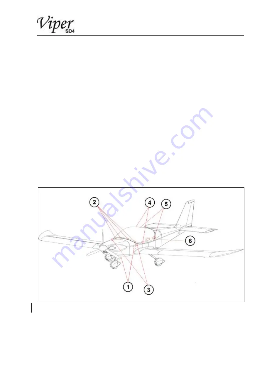
The air entering through the cockpit air inlets (1) is directed by plastic
tubes to the air vents (2) above of the instrument panel and to two air
nozzles (3) located on left and right instrument panels. The air
nozzles are controllable with ability to be closed by rotary motion.
Canopy glass ventilation is supplied by two canopy air inlets (4). The
airflow is led to the air vents located on the front part of the cabin
frame and is adjustable by valves (5) located at the sides of canopy
frame.
The canopy is equipped with ventilation windows (6) on the sides.
Figure 5
Ventilation scheme diagram


