background image


24 


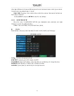
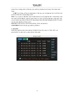
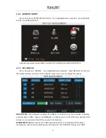
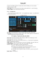
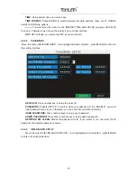
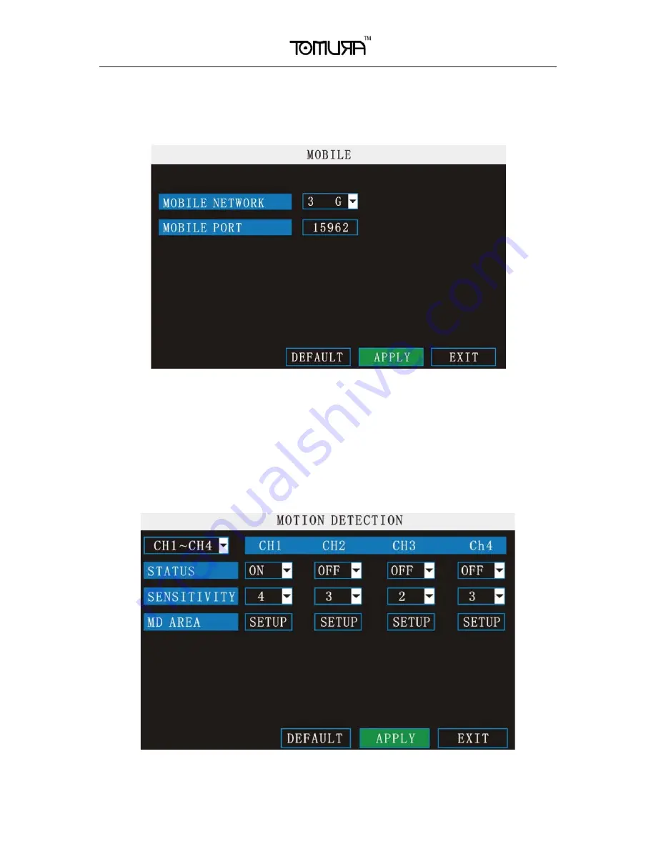
2.2.3.5   MOBILE 

Move the cursor to

Ǐ

MOBLE

ǐ˄

Icon highlighted when selected

˅

,press

Ǐ

Enter

ǐ

to enter into 

setting interface.   


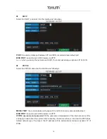
CHANNEL SELECTION:

 select the channel for mobile view, and press [Enter] to switch 

different channels. 

MOBLESS LAN:

 Select different mobile network from the options of 3G, 2.5G and 2.75G, 

and press [Enter] to switch different network. 

PORT:

 the port for mobile view, you should open the port in the router for mobile view. 


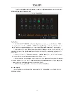
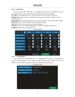
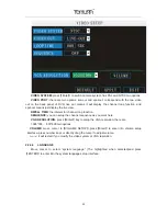
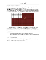
2.2.3.6   MOTION DETECT 

Move the cursor to

Ǐ

MOTION DETECT

ǐ˄

Icon highlighted when selected

˅

,press

Ǐ

Enter

ǐ

to enter into setting interface.   


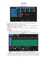
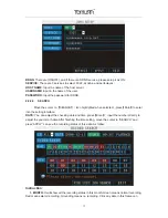
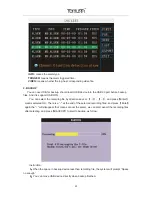
CH1~CH4:

 you can select the CH1~CH4, CH5~CH8, CH9~CH12, CH13~CH16 here. 

STATUS:

 Each channel has corresponding channel switch, press


Ǐ

Enter

ǐ

to turn on or turn off 

Summary of Contents for PS-8316B

Page 1: ......

Page 2: ...N 11 2 2 2 GUI OPERATION 12 2 2 3 DEVICES SETUP 21 2 2 4 SYSTEM SETUP 27 3 IE OPERATION 31 3 1 FEATURE 31 3 2 USER LOGIN 31 3 3 OPERATION INTERFACE 32 3 3 1 LIVE 32 3 3 1 1 PTZ CONTROL 32 3 3 1 1 1 ZOOM 33 3 3 1 1 2 PTZ PRESET 33 3 3 1 2 PLAY 33 3 3 1 3 OTHER OPERATION 33 3 3 2 REPALY 34 3 3 3 SETUP 36 3 3 3 1 RECORD 36 3 3 3 2 ALARM 37 3 3 3 3 PTZ 38 3 3 3 4 NETWORK 38 3 3 3 5 SETTING 39 3 3 3 6 ...

Page 3: ...UHVVLRQ 86 LQWHUIDFH ࡁᕍࡤ 86 ࡡࢀࡩ ࡢࡨࡑࡡࢀࡩ ࡤ ᕎࡤࡘࡰ 86 ࡡࢀࡩࡢ ࡨࡑࡳࡘࡩࡡᕑ ರ 6 7 ࡰ ࡧࡑࡑࡷࡖ ᕑ VHFXULW ࡕ ࡳ ࡠ ࡳࡘࡐࡰ 8 ࡶࡁᕎ ࡩࡐ ᕍࡩ ࡤ ࡨࡑ ࡩ SOD EDFN ࡁᕍࡤ ࡕ ᕎࡤࡘ ࡨࡐ ࡧࡑࡑ XVHU PDQDJHPHQW ࡡࡤ ࡧࡋࡨࡑ ࡡࡐࡨࡑࡡࡐ ࡐ OLYH YLHZ ࡌࡨࡼ ᕍࡩ SDUDPHWHU ࡴ ࡧ FRS SOD EDFN YLGHR ࡓᕍࡩࡐ QHWZRUN 1 2 1 SPECIFICATION Item Device performance index System Language Thai Chinese English GUI Graphic menu password user password administrator password Video Video ...

Page 4: ...Audio style ADPCM Video code rate CIF 384Kbps 768Kbps 8 level optional 1 is highest 8 is lowest Audio code rate 32KB s Data storage Support all kinds of storage HDD Alarm Alarm input 8 alarm input Alarm output 1 alarm output Connector Serial interface Support 1 RS232 Serial interface Support 1 RS485 Network interface RJ45 10M 100M USB Mouse USB1 1 Thumb drive USB2 0 VGA VGA 1 VGA optional Software...

Page 5: ... 30v High voltage alarm RS232 serial port for extend use RS485 Connect to PTZ Pelco D Pelco P SATA HDD 2 SATA with maintain capability 1 3 ENTIRONMENT ADAPTABILITY ࡳࡕ ࡻࡤ ࡩ ࡶࡁᕎ ࡩࡐࡎ ࡻࡳࡢࡘࡩࡧࡡࡘ ࡨࡑࡳ ࡻࡤ ࡴ ࡧ ࡋࡤࡩ ࡩ ࡶࡁᕎ ࡩࡐࡤ ࡒ ࡊᕑ ࡊࡧࡌ ࡋࡌࡨࡼ ࡤ ࡒ ࡊᕑ ࡵࡒ ࡋࡎࢀࡩࡌࡩࡘࡘࡩࡌ ࡇࡩࡐ ࡩࡘࡒ ࡤࡋࡗࡨ ࡤ ࡒ ࡊᕑࡷࡖࡖᕉࡩ ࡷࡖࡳ ࡼ ࡢᕎࡩࡘࡳࡒᕄࡋࡡ ࡎࡂᕑ 95 ࡊࡧࡘ ࡤࡳࡒᕅ ࡢᕎࡩࡘࡳࡎ ࡤ ࡳࡢ ࡶࡋࡹ ࡳ ࡻࡤ ࡤ ᕍࡩ ࡩ ࡂᕎࡤࡐࡳ ࡻࡤ ࡶࡁᕎࡓᕎࡩࡴࡢᕎ ࡐ ᕍࡘࡎࢀࡩ ࡩࡘࡡࡧࡤࡩࡋ ࡤ ᕍࡩࡶࡁᕎࡐࡼࢀࡩ ࡩࡳ ࡘ ࡶࡋࡹ ...

Page 6: ... 2 DEVICE OPERATION ࡒ ᕈࡘ 17 5ࡑࡐ ࡵࡘࡎࡳࡒ ࡑࡳࡡࡘ ࡤࡐ ࡩ ࡂᕎࡩ ࡎ ࡻࡳࡘࡩࡡᕑ 2 1 REMOTE KEY INSTRUCTION 2 1 1 REMOTE CONTROL Handheld IR Controller Key Functions Ǐ0ˉ9ǐkeys ࡊࡧࡎࢀࡩ ࡩ ࡌࡨࡼ ᕍࡩ ࡶࡁᕎࡒ ᕈࡘࡳࡢ ᕍࡩࡐ ࡼࡶࡡᕍ ᕍࡩࡌࡨ ࡳ ࡋࡨ ࡐ ࡼ ...

Page 7: ...ࡖ ࡘ ࡋ 7 ࡳࡕ ࡻࡤ ᕎࡤࡐࡢ ࡨࡑࡷࡒ ࡩࡳ ࡺ ࡳ ᕍࡐ ᕎࡤࡐࡢ ࡨ ࡒ ࡌ ǏFWDǐ ࡳ ᕍࡐࡗࡩࡕ ᕎࡤࡐࡢ ࡨ ࡷࡒ ᕎࡩ ࡢࡐᕎࡩࡎ ࡻࡵࡢࡘࡋ ࡢ ࡤ ࡋ ࡳࡕ ࡻࡤࡳ ࡤ ࡋ ᇻ 3 ᇼࡳࡕ ࡻࡤ ࡨࡑࡡࡰᕍ ࡩࡘࡳ ࡺ ࡒ ࡌ ǏREVǐ ᕎࡤࡐࡗࡩࡕ ࡋ ࡵࡤ ࡊࡧࡳ ᕍࡐ ᕎࡤࡐࡢ ࡨ ࡵࡋ ࡘ ࡡ ࡻࡵࡢࡘࡋ ࡋ 5 ࡳࡕ ࡻࡤࡳ ࡤ ࡋ ᇻ3 ᇼࡳࡕ ࡻࡤ ࡨࡑࡡࡰᕍ ࡩࡘࡳ ࡺ ࡒ ࡌ ǏSTANDBYǐ ࡶࡁᕎࡳࡒᕄࡋࡒᕄࡋ 95 VWDQGE ࡴ ࡧ VWDUW XS ǏLOGIN LOCKǐ ࡍᕎࡩ ࡧࡑࡑ VHFXULW ࡍࡰ ࡌࡨࡼ ᕍࡩࡌࡤࡐ VHWXS ࡶࡢᕎࡶࡁᕎࡒ ᕈࡘ 2 1 2 ࡳࡕ ࡻࡤࡳ ᕎࡩࡡࡰᕍ XVHU VHWXS ࡵࡒ ࡋ ࢀࡩ ࡢࡨࡡࡓᕍࡩࡐࡷ ᕎࡳࡕ ࡩࡧࡷࡘᕍࡘ ࡖᕓ ᕑࡁࡨࡻࡐࡁᕍ ࡢࡩ ࡘ RJ LQ ࡤࡢࡐ...

Page 8: ...LYH YLHZ ࡢ ࡤ SOD EDFN ࡴࡑࡑࡢ ࡩ ࡢࡐᕎࡩࡌᕍࡩ ᕍࡤ ࡒ ࡨࡑ 9ROXPH ࡡ ࡌࡨࡼ ᕍࡩ 37 ࡴ ࡧ 9 ࡶࡁᕎࡌࡨࡼ 9ROXPQ ࡳࡀࡕࡩࡧࡢࡐᕎࡩࡌᕍࡩ ࡳࡋ ࡑ ࡘ 37 ࡴ ࡧ ࡒ ࡨࡑࡡ ࡢࡩ ࡤ ࡰᕍࡶࡐࡵࡢࡘࡋࡢ ࡩ ࡢࡐᕎࡩࡌᕍࡩ ᕍࡤ ࡶࡢᕎ ࡂᕎࡩ ࡳࡕ ࡻࡤࡳ ࡤ ࡢࡐᕎࡩࡌᕍࡩ ࡳ ࡻࡤ ࡢࡘࡩ ࡳࡘ ࡻࡤ ࡒ ࡨࡑ 9ROXPQ ࡢ ࡤ ࡒ ࡨࡑ ࡡ ࡢ ࡤ 9 ERUGHU ࡳࡒᕕࡐࡋࡨ ࡐ ࡼ D ࡘ ࡴ ࡧ ࡎ ࡻࡢࡐᕎࡩࡌᕍࡩ 37 VHWWLQJ ࡳࡕ ࡻࡤࡒ ࡨࡑ ᕍࡩ SDUDPHWHU E ࡂᕎࡩ ࡎ ࡻࡁᕍࡤ ࡡࡨࡄࡄࡩࡊࡎ ࡻࡌᕎࡤ ࡩ ࡴ ᕎ ࡧࡳࡢࡺࡐࡳࡘࡐࡰࡋᕎࡩࡐ ࡩࡶࡢᕎࡒ ࡨࡑ YROXPH ಯ ರ ࡳࡕ ࡻࡤࡤࡤ F ࡒ ࡨࡑࡡ ࡴ ࡧ 9 ERUGHU ࡩ ࡎࢀࡩ ࡩࡐࡶࡢᕎࡋࡰ ࡏ ࡩ ࡒ ...

Page 9: ... ERDUG ࡳࡘ ࡻࡤࡳ ࡤ ࡶࡁᕎࡗࡩࡠࡩ ࡐ ࡏ ࡶࡁᕎ ࡩࡐ ࡧࡳࡢࡘ ࡤࡐ 5 UHPRWH FRQWUROOHU ࡊࡡࡩࡘࡩ ࡍࡶࡁᕎࡒ ᕈࡘ ࡂᕎࡩ ࡩ ࡳࡕ ࡻࡤࡳ ࡻࡤࡐࡢࡐᕎࡩ ࡊࡧ ᕎࡐࡢࡩࡤࡨ ࡠ 3LQ LQ KLQHVH ࡩ ࡶࡡᕍࡌࡨ ࡳ ࡩ ᕑࡑࡤ ᕑࡋࡳࡡࡘ ࡤࡐ ࡧࡍࡰ ࡳ ࡶࡢᕎࡳ ࡤ ࡌࡨ ࡳ ࡎ ࡻࡌᕎࡤ ࡩ µ Á µ r ࡋࡒ ᕈࡘࡂᕎࡩ ࡳࡕ ࡻࡤ ᕎࡩ ࡳࡘࡩࡡᕑࡶࡢᕎࡡࡩࡘࡩ ࡍࡒ ࡨࡑ ᕍࡩ 9ROXPH ࡡ ࡢࡐᕎࡩࡌᕍࡩ 9 ERUGHU ࡴ ࡧ ࡕࡩ ࡩࡘ ࡳࡌࡤ ᕑࡌᕍࡩ ࡹ ࡧࡍࡰ ࡴࡡࡋ ࡳࡤ ࡎ ࡻࡢࡐᕎࡩࡌᕍࡩ 0RWLRQ HWHFWLRQ VHWWLQJ ࡊࡡࡩࡘࡩ ࡍࡶࡁᕎࡒ ᕈࡘࡂᕎࡩ ࡩ ࢀࡩࡢࡐࡋࡕ ࡼࡐࡎ ࡻࡡࢀࡩࡢ ࡨࡑ ࡌ ࡨࡑ ࡩ ࡳ ࡋ ࡩࡘࡳ ࡻࡤࡐࡷࡢ ...

Page 10: ...10 2 1 3 MENU TREE ࡊࡡࡩࡘࡩ ࡍ ࡑ ࡘ 95 ࡋᕎ ࡳࡘࡐࡰࡌᕍࡩ ࡹࡋࡨ ࡐ ࡼ ...

Page 11: ...ࡌ ࡋࡌࡨࡼ ࡳࡒᕕࡐ ࡨࡼ ࡴ 2 SYSTEM LOGIN ࡳࡘ ࡻࡤ ࡊ ORJLQ ࡧࡕࡑࡢࡐᕎࡩࡌᕍࡩ ࡋࡨ ᕎࡩ ᕍࡩ ࡍᕎࡩࡘ ࡩ ࡌࡨࡼ SDVVZRUG ࡷ ᕎ ࡶࡢᕎࡶࡡᕍ GHYLFH ࡴ ࡧ XVHU SDVVZRUG ࡴ ᕎ ࡋ ᇻ SSO ᇼ ᕎࡤ ࢀࡩ ࡳࡕ ࡻࡤࡶࡢᕎࡡࡩࡘࡩ ࡍ ࡨࡋ ࡩ ࡤ ࡒ ࡊᕑࡡࡧࡋ ࡶࡢᕎࡌࡨࡼ ᕍࡩ XVHU SDVVZRUG ࡴ ࡧࡳࡒ ࡻ ࡐ GHYLFH ࡳࡘ ࡻࡤ VHWXS ࡨࡼ ࡴ ࡊࡡࡩࡘࡩ ࡍࡌࡨࡼ ᕍࡩ 8VHU ࡴ ࡧ DGPLQ SDVVZRUG GPLQLVWUDWRU ࡡࡩࡘࡩ ࡍࡎࢀࡩࡷࡋᕎࡎ ࡤ ᕍࡩ RSHUDWRU ࡧࡍࡰ ࢀࡩ ࡨࡋࡡ ࡎࡏ ࡶࡢᕎࡡࡩࡘࡩ ࡍࡋࡰࡗࡩࡕ ࡴ ࡧ SOD EDFN ࡵࡒ ࡋࡳࡒ ࡻ ࡐ XQLW ࡴ ࡧ GHIDXOW SDVVZRUG ࡳࡕ ࡻࡤ ࡩࡘࡒ ࡤࡋ...

Page 12: ...ARCH DEVICES Â SYSTEM ᕎࡤ ࢀࡩ ࡢ ࡨ ࡩ ࡒ ࡨࡑ ᕍࡩࡌᕎࡤ ࡋ ಯ 33 ರ ࡩ ࡌࡨࡼ ᕍࡩࡌᕍࡩ ࡹ ࡧࡍࡰ ࡨࡋࡳ ࡺࡑ ࡴࡌᕍࡢࡩ ࡋ LW ࡧࡷࡘᕍࡘ ࡩ ࡨࡋࡳ ࡺࡑ ࡡࢀࡩࡢ ࡨࡑ 95 ᕍࡐࡐ ࡼࡳࡘ ࡻࡤ ᕎࡩ ࡳࡘࡩࡡᕑ ࡩ ࡎ ࡻࡢࡐᕎࡩࡷࡤ ࡤࡐࡶࡋࡹ ࡧࡘ ᕎࡤ ࡩࡘࡤࡏ ࡑࡩ ࡴࡡࡋ 2 2 2 1 CAMERA ࡳ ࡤ ࡷࡤ ࡤࡐǏCAMERAᇼ ࡳࡘ ࡻࡤࡳ ࡤ ࡩ ࡩ FRQ ࡧࡘ ࡴࡍࡑࡡ ࡴ ᕎ ࡋǏEnterǐࡳࡕ ࡻࡤࡳ ᕎࡩࡢࡐᕎࡩࡌᕍࡩ ࡌࡨࡼ ᕍࡩ ...

Page 13: ...WQHVV FRQWUDVW ࡴ ࡧ VDWXUDWLRQ ࡶࡢᕎ ࡋᇻ 33 ᇼࡳࡕ ࡻࡤࡑࡨࡐࡎ ᕍࡩ LIVE ON ࡁᕍࡤ ࡡࡨࡄࡄࡩࡊࡐࡨࡼࡐࡹ ࡧࡡࡩࡘࡩ ࡍࡋࡰࡶࡐࡵࡢࡘࡋ OLYH PRGH ࡷࡋᕎ 2 ࡢࡘࡩ ࡩࡘ ᕍࡩࡋࡰࡷࡘᕍࡷࡋᕎ DISPLAY TIME WHILE IN LIVE VIEW 21 ࡶࡢᕎࡴࡡࡋ ࡳ ࡩ ࡊࡧ OLYH YLHZ 2 ࡷࡘᕍࡴࡡࡋ DISPLAY TIME WHILE RECORDING 21 ࡶࡢᕎࡴࡡࡋ ࡳ ࡩ ࡊࡧ5HFRUG YLHZ 2 ࡷࡘᕍࡴࡡࡋ 2 2 2 2 RECORD SETUP Move the cursor to ǏRECORDǐ Icon highlighted when selected pressǏEnterǐto enter into the setting interface PressǏConf...

Page 14: ...audio recording REC MODE POWER UP Means the device will start recording when it startup TIME Recording as the schedule you can setup the schedule as you want as follow CHANNEL You can select all channels or just one channel to setup schedule WEEKLY You can setup each as you want There are ALARM NORMAL NO REC three modes if you select this there will have a in the frame that means when you select t...

Page 15: ... the cursor to NETWORK SETUP icon highlighted when selected and press ǏEnterǐ to enter into setting interface TYPE There are PPPOE DHCP Static three options ƽ STATIC Select Static in the type and press Enter to enter into the interface as followings PORT For video transmission via IE WEB PORT setup the port of IE browser via HTTP IP ADDRESS setup the IP address and press Enter or number keys to ch...

Page 16: ...DVR ƽ PPPOE Select the PPPOE and enter the interface as followings MEDIA PORT the communicate port between PC and DVR recommend use default port WEB PORT setup the port of IE browser via HTTP PPPOE username and password fill the username and password of the internet service offer and apply it and reboot the system After rebooting the device will save it and set the PPPOE as default network type If...

Page 17: ...con highlighted when selected press ǏEnterǐ to enter into the setting interface DATE You can adjust the checking date and time pressǏEnterǐ input the number directly to adjust the year month date After finishing the time setting move the cursor to SEARCH and press APPLY can see the recording status of this date As follow Instruction 1 MONTH It will show all the recording status in this month Green...

Page 18: ...fter setting move the cursor to PLAYBACK and then press APLLY to enter into video playback of that time Also you can select any period of time in the video status frame after searching press APLLY to enter into the video playback of this period FILE LIST Enter into the video file list interface of the selected date LOG SEARCH Enter into the log searching interface 1 FILE LIST Setup the searching d...

Page 19: ...to enter into playback interface If the all channels have recording files it will be playback all windows at the same time 3 If setup as on in theǏRECORD TIMEǐin ǏBASIC SETUPǐ it will show the date time when playback record file If setup as off it will not display time 4 When playback can pressǏSLOWǐto play slowly pressǏFORWARDǐandǏREVERSEǐ to speedǃ reverse play also can press ǏPAUSE STEPǐ to pau...

Page 20: ... recording file by direction keys or ǏˇǐǃǏˉǐ and pressǏEnterǐ means selected OK There is a at the end of the selected recording files and pressǏEnterǐ again the will disappear that means cancel the select we can start export the recording files after selecting and pressǏBACKUPǐto start to backup as follow Instruction 1ˊ When the space in backup device less than recording file the system will promp...

Page 21: ...er into the setting interface and you can use direction keys and cursor to change the options HDD STATUS There status is ok means the HDD is ok If HDD can not run normally including unformat and no HDD there is aǏHǐ display on video live view 16CH DVR can support 4 HDD at most so you can select the HDD you want to format here OVERWRITE ENABLE means when HDD space less than 4G it will delete HDD ea...

Page 22: ... low effective N C indicate I O input level from low to high effective HDD LOSS ON means it will trigger a alarm if there is no HDD and it will display an ǏHǐ On the bottom left of channel 1 in the live view HDD SPACE ON If the space less than 500M there is a o ª ε in live view No enough space please change HDD after shutdown VIDEO LOSS ON when one channel has no video input it will display video...

Page 23: ...he different baud rate for your PTZ there are 1200 2400 4800 and 9600 DATA BIT there are 5 6 7 8 options to select default setting is 8 STOP BIT there are 1and 2 to select the default setting is 1 VERIFY there are None Odd Even Mark Space to select the default setting is none ADDRESS Fill the code of respective PTZ 2 2 3 4 SYSTEM INFO Move the cursor to ǏSYSTEM INFOǐ Icon highlighted when selected...

Page 24: ...ork from the options of 3G 2 5G and 2 75G and press Enter to switch different network PORT the port for mobile view you should open the port in the router for mobile view 2 2 3 6 MOTION DETECT Move the cursor toǏMOTION DETECTǐ Icon highlighted when selected pressǏEnterǐ to enter into setting interface CH1 CH4 you can select the CH1 CH4 CH5 CH8 CH9 CH12 CH13 CH16 here STATUS Each channel has corres...

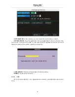
Page 25: ... activated motion detection Move the direction key on remote control to make cursor move in the small pane green frame means the cursor has moved to this pane pressǏEnterǐto select or cancel motion detection of this small pane when setup finished press Ǐexitǐ to back to MD setup interface it will save automatically o ª ε IR Operation press Menu key to select or cancel the entire screen Mouse oper...

Page 26: ...tory of the thumb driver and insert it into USB 1 0 then press Enter to upgrade the firmware and it will display the process of the system upgrading as following LOAD DEFAULT Restore all the settings as the factory setting REBOOT means restart the device 2 2 3 8 EXIT Move the cursor to ǏEXITǐ Icon highlighted when selected press ǏEnterǐ to back to main menu ...

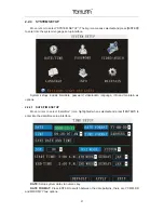
Page 27: ...include time date password video audio language info and maintain six options 2 2 4 1 DATE TIME SETUP Move cursor to select date time icon highlighted when selected and pressǏENTERǐto enter into the date time setup interface DATE Setup system date via numeric key DATE FORMAT Press ENTER to switch between the date patterns there are YY MM DD and MM DD YY two options ...

Page 28: ...ess ǏEnterǐ to enter into the setting interface DEVICE ID Press number key to setup the unite ID PASSWORD PressǏAPPLYǐ to start or close user password If it is ENABLE you must input password when log in otherwise you can enter into main Manu directly USER PASSWORD Press number keys to setup user password ADMIN PASSWORD Press press number keys to setup admin password NETWORK PW CLEAN Means the pass...

Page 29: ...function SEQUENCE you can setup the channel sequence as you want here VGA RESOLUTION pressǏEnterǐkey to setup the VGA resolution there are 1024 768ǃ 800 600 two options VOLUME move cursor toǏVOLUME SETUPǐ pressǏEnterǐto enter into volume setup interface press number keys or directly drag the cursor to adjust volume o ª ε it will restart if you modify the video system or VGA resolution 2 2 4 4 LAN...

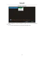
Page 30: ...30 System language have Chinese and English two options you can setup the language you want in here o ª ε The device will restart when you setup system language success ...

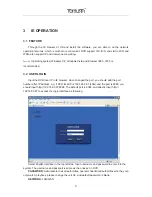
Page 31: ...ed the port you should add the port number after IP address e g if DVR local IP is 192 168 3 97 LAN and the port is 8088 you should input http 192 168 3 97 8088 The default port is 8088 and directly input http 192 168 3 97 to access the login interface as following Select English interface in the top left side Input username and password to enter into the system The username and passport is same a...

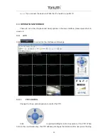
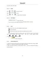
Page 32: ...in the main interface please press them to access it 3 3 1 LIVE Click to enter into the interface as followings 3 3 1 1 PTZ CONTROL Change the focus preset aperture to control the PTZ Click to up down left right control movement of the PTZ When hold on the one direction key the PTZ will keep circling as that direction after user press the stop ...

Page 33: ...cal disk the default save path is C DVR Quickly start all channels recording video here the left up corner of each channel have normal recording video symbol Ǐ R ǐ click icon to switch between single screen quad nine 16 split Volume adjust button 3 3 1 3 OTHER OPERATION 1 Select one channel at preview screen the selected channel s frame will be change to RED double oµ enter to the selected channel...

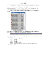
Page 34: ... close all windows will quickly open close all windows 3 3 2 REPALY Click to enter into remotely playback interface which is to playback the record file in DVR Click right up of calendar interface and to setup the month for searching click refurbish at the calendar interface will display the recording information of current month ...

Page 35: ...c At the below of calendar select channel and type click SEARCH the result will display as follow Double click one item of listed recording video the recording video will playback meanwhile the file icon will change to and will occur the below picture play buttons The above purple progress bar shows download progress green progress bar shows playback progress Switch between pause play Stop play Fa...

Page 36: ...ick file convert start the convert progress bar see below picture will see the progress of convert 3 3 3 SETUP Click to enter into setup interface this interface include record alarm PTZ network setting and system information six menus 3 3 3 1 RECORD Click to enter into setup interface you can check the parameter settings as in GUI of DVR ...

Page 37: ...37 3 3 3 2 ALARM Click to enter into setup interface you can check the parameter settings as in GUI of DVR ...

Page 38: ... 3 3 3 PTZ Click to enter into setup interface you can check the parameter settings as in GUI of DVR 3 3 3 4 NETWORK Click to enter into setup interface you can check the parameter settings as in GUI of DVR ...

Page 39: ...the parameter settings as in GUI of DVR BANDWIDTH Set the amount of bandwidth in kbps 128kǃ 192kǃ 256kǃ 384kǃ 512kǃ 1024k that you want to allocate for traffic that matches internet this bandwidth not include audio o ª ε the normal ADSL network is between 256k and 384k ...

Page 40: ... setup the password when you login IE DST settings you can check as DVR setting 3 3 3 6 HOST INFO Click to enter into system information interface see below picture this interface shows HDD status remain record time firmware version MAC Address and all the information is fixed ...

Page 41: ...ttons on Front Panel Item Silk Screen Description 1 ON OFF POWER ON OFF 2 Mouse USB mouse 4 REC Recording ALARM Alarm HDD1 HDD1 Status HDD2 HDD2 Status HDD FULL On means the HDD is full 100M On means network is 100M LINK On means network has connected ERROR Error POWER Power 5 IR Remote control receiver ...

Page 42: ... video output for connecting TV or monitor BNC 4 Video input For connecting analog video signal input BNC 5 Audio Input For connecting audio signal 6 Alarm Input 8 I O alarm input Alarm Output I O output for alarm RS485 RS 485 for connecting PTZ RS232 For connecting PC 7 Network For connecting Ethernet 8 VGA For connecting VGA monitor 9 Audio Output For connection audio output 10 USB USB2 0 USB mo...

Page 43: ...43 3 Connectors for Alarm Peel off the color skin of the cable and then insert the cable into the slot on the rear panel DVR The connection part for alarm ...

Page 44: ...for this DVR Alarm input is for connection IR annunciator fog sensor The connection diagram of DC alarm input as following Connection diagram of AC alarm input as following The connection diagram of alarm output as following 5 System Network Diagram RELAY 220V AC 12V 24V DVR I O output ...

Page 45: ...45 ...
Page 46: ...pen the cover of the DVR and then you will see one HDD plate as follow 2 Connect HDD line as follow 3 Affix HDD on HDD plate as indicated below with the screws around 4 Install the HDD plate back into DVR and close cover Notice Newly installed HDD should format before recording ...

Page 47: ...e hardware of DVR is defective 3 Question No output of single channel multi channel or all channel video Answer Please check the adaptor of camera whether to see if it is well connected Please check the cable for connecting video input output in the back panel of DVR Please insert the video source directly into the display device and check If they are causing the problem Check the brightness of th...

Page 48: ...when playing back Answer Setting problem open audio video item Check the audio to see if it is closed in playback interface 9 Question System time is not correct Answer Wrong setting or user did not click Edit to confirm Battery is not connected properly Battery is dead Please change 10 Question Why the Stop recording by the right mouse button does not work how to stop recording Answer The Stop re...

Page 49: ... LED is displayed normally on the panel use ping xxx xxx xxx xxx DVR IP to check if the Internet is linked properly Recommended to use Windows XP or Vista operating system also use IE6 0 browser or IE7 0 browser ActiveX control has been blocked Please manually install ActiveX control again Please install DX8 1 and upgrade your video card driver 16 Question There is no picture or picture is not cle...

Reviews: