28
Make use of the
key or the knob to move the cursor to this parameter option, then change it with
the front panel numeric keys, and finish with ENTER or OK keys to confirm the change. If you do not
want to change the parameter value or press the wrong numeric key when changing with the numeric
keys, you can cancel it by pressing the
key or ESC key.
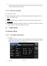
IRMS_L
1)
Description
The parameter represents the current lower limit setting. When the set voltage is not greater than
150V, the range is 0.000~8.400A; When the set voltage is greater than 150V, the range is
0.000~4.200A. When the “PLC Onoff” under <SysSetup> SysCom page is set to ON, and IRMS_L is not
0, if current output is less than IRMS_L, “FAIL” will be displayed after the output ends; If the output
current is greater than or equal to IRMS_L, “PASS” will be displayed after the output ends. For details,
see the result display function and remote control signal output function. When set to 0.000, the
IRMS_L function is turned off.
2)
Operation
Make use of the
key or the knob to move the cursor to this parameter option, then change it with
the front panel numeric keys, and finish with ENTER or OK keys to confirm the change. If you do not
want to change the parameter value or press the wrong numeric key when changing with the numeric
keys, you can cancel it by pressing the
key or ESC key.
FREQ
1)
Description
This parameter is used to set the output frequency. The range is 45.0~500Hz. When the frequency is
less than 100 Hz, the resolution is 0.1 Hz; when the frequency is not less than 100 Hz, the resolution is
1 Hz.
2)
Operation
Make use of the
key or the knob to move the cursor to this parameter option, then change it with
the front panel numeric keys, and finish with ENTER or OK keys to confirm the change. If you do not
want to change the parameter value or press the wrong numeric key when changing with the numeric
keys, you can cancel it by pressing the
key or ESC key.
Connect
1)
Description
This parameter is used to indicate whether the current step is connected to the current memory
sequence. When the step connection of the 1st step of the memory 1 is set to "OFF", even pressing
the ON/OFF button will not enter the test; When the step connection of the 1st step of the memory 1
is set to "ON", the step connection of the 2nd step of the memory 1 is set to "OFF", the test is stopped
after the test is passed in the 1st step of the memory 1; When the step connection of the 1st step of
the memory 1 is set to "ON", the step connection of the 2nd step of the memory 1 is set to "ON", after
the test is passed in the 1st step of the memory 1, the test will automatically proceed to the 2nd step.
If the step connection is set to "ON", "*" will be displayed after “Memory” in <MeasDisp> page. The
Summary of Contents for TH7105
Page 14: ...9...

