background image


11 


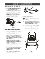
INSTALLING THE DUST BAG ASSEMBLY 
 

1.  Insert the dust duct bag assembly sleeve 

(1) into the dust chute (2) (Fig. 1).  

NOTE: Make sure the tabs (3) insert into 

the matching slots (4) in the dust chute. 


2.  Rotate the dust chute sleeve CLOCKWISE 

approximately 15° to lock it into place. 

NOTE: Remove and clean the dust bag 

assembly periodically to remove 

accumulated dust from the dust bag. 


REMOVING & CLEANING THE DUST BAG 


1.  Remove dust bag assembly by rotating the 

dust bag assembly approximately 15° 

counter clockwise and pulling it out of the 

dust chute in the sander. 


2.  Remove the dust bag (1) from the dust bag 

support (2) by opening the elasticized end 

of the dust bag (3) and sliding it off the dust 

bag support (Fig. 2). 


3.  Carefully shake the dust bag with the 

elasticized opening pointing downward to 

remove the sanding dust. 

NOTE: It is best to perform this function 

outdoors over a trash can to prevent 

sanding dust from escaping into the work 

area. 


4.  Once the sanding dust is removed from the 

dust bag, reinstall the dust bag onto the 

dust bag support. 


5.  Reinstall the dust bag assembly into the 

dust chute as noted above. 


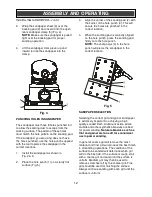
INSTALLING SANDPAPER 


WARNING:

 Unplug the sander from the 

power source before installing or changing 

the sandpaper. 


1.  Lift up and outward on the front and rear 

sandpaper clamp levers (1) at the front and 

rear of the backing pad (2) (Fig. 3). 


2.  Insert one end of the ¼ sheet sandpaper 

(3) with grit side up into the open front 

sandpaper clamp (4), making sure it is 

aligned with the backing pad. Lift the 

sandpaper clamp lever up and inward to 

lock the sandpaper into the clamp.


ASSEMBLY AND OPERATING 

Fig. 1 


Fig. 2 


Fig. 3 


Summary of Contents for 241-9946

Page 1: ...T SPECIFICATIONS Rating 120 V 60 Hz AC Amperes 1 5 A Speed 13 000 OPM no load Sanding pad size 1 4 sheet Need Assistance Call us on our toll free customer support line 1 866 349 8665 Technical questio...

Page 2: ...6 Power tool use and care 6 Service 6 Specific safety rules 7 Guidelines for extension cords 8 Symbols 9 Know your palm sander 10 Assembly and operating 11 14 Installing the dust bag assembly 11 Remo...

Page 3: ...eyewear can cause serious injury if broken during the operation of a power tool WARNING Use hearing protection particularly during extended periods of operation of the tool or if the operation is nois...

Page 4: ...r The level of risk from exposure to these chemicals varies according to how often this type of work is performed In order to reduce exposure to these chemicals work in a well ventilated area and use...

Page 5: ...ctric shock If operating a power tool in a damp location is unavoidable use a residual current device RCD protected supply Use of a ground fault circuit interrupter GFCI reduces the risk of electric s...

Page 6: ...ions to operate the power tool Power tools are dangerous in the hands of untrained users Maintain power tools Check for misalignment or binding of moving parts breakage of parts and any other conditio...

Page 7: ...ding WARNING Always use hearing protection when sanding particularly during extended periods of operation WARNING Always unplug the tool from the power source before changing the sandpaper and when cl...

Page 8: ...otected with either a 15A time delay fuse or circuit breaker Before connecting the power tool to the power source make sure the switch is in the OFF position and the power source is the same as indica...

Page 9: ...e alternating current Three phase alternating current with neutral Direct current No load speed Alternating or direct current Class II construction Splash proof construction Watertight construction Pr...

Page 10: ...10 KNOW YOUR PALM SANDER Backing pad Palm grip Dust bag assembly Sandpaper clamp Sandpaper clamping lever ON OFF switch Cooling vents Sandpaper hole punch Sandpaper 1 sheet each 60 80 120...

Page 11: ...arefully shake the dust bag with the elasticized opening pointing downward to remove the sanding dust NOTE It is best to perform this function outdoors over a trash can to prevent sanding dust from es...

Page 12: ...les are punched in the correct location 4 When the sanding pad is correctly aligned on the hole punch press the sanding pad firmly onto the hole punch NOTE The sharp pegs 4 in the hole punch will pier...

Page 13: ...n the sander ON by pressing on the side of the ON OFF switch Move the sander slowly over workpiece making successive passes in parallel lines circles or crosswise movements Because the orbital motion...

Page 14: ...the sander usually provides adequate pressure Let the sander and the sandpaper do the work Applying added pressure will slow the motor increase the wear on the sandpaper and greatly reduce the sander...

Page 15: ...cted to accelerated wear and possible premature failure when they are used on fiberglass boats and automotive parts wallboard spackling compounds or plaster The chips and grindings from these material...

Page 16: ...EXPLODED VIEW 16...

Page 17: ...28 Stator 1 9 4010010034 Bearing 1 10 3011080023 Housing right 1 11 4030010106 Tapping screw 6 12 1250010002 Wiring terminal 1 13 4030010099 Tapping screw 2 14 3150020001 Strain relief 1 15 3140010054...

Page 18: ...ts This warranty does give you specific legal rights and you may have other rights which vary from state to state Be careful tools are dangerous if improperly used or maintained Seller s employees are...

Reviews: