background image

Guidance MP-888 - Supplement to the manual of instructions 

4/10 


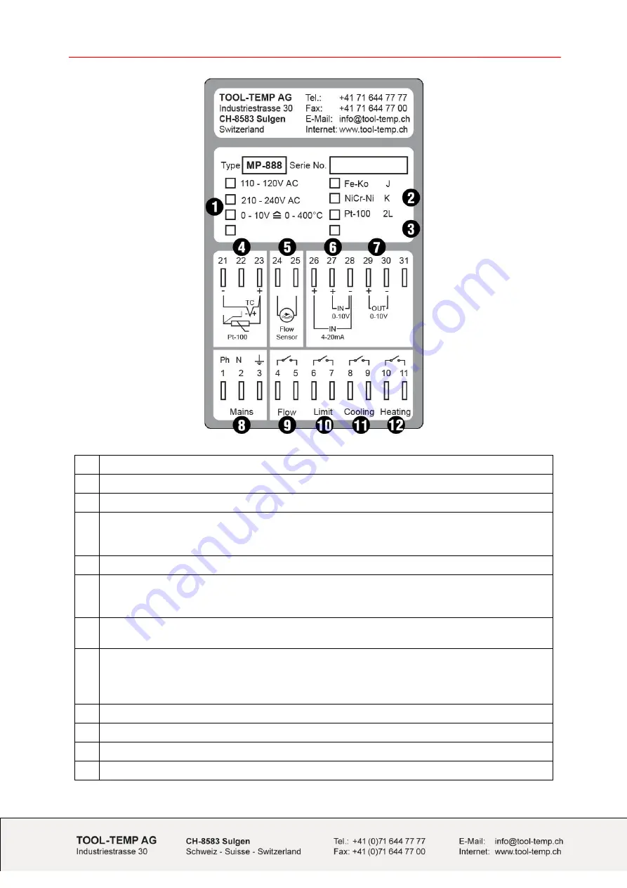
1  Possible supply voltages  

(factory adjusted)


2  Possible temperature sensor

  (factory adjusted) 

3  Version of the controller 

4  Temperature sensor connection 

21+23  

Temperature sensor  

– note  + / - 

22 

Pt-100 compensation


5  Flow control 

– encoder signal 

6  Connection external set point  

26+28 

Analog input  4- 20mA 

27+28 

Analog input  0 - 10 V 

7  Connection actual value - output  

29+30 

Analog output 0 - 10V 

8  Power supply 

230V AC 

Neutral 

PE


9  Flow control (alarm) 

10  Temperature monitoring, temperature deviation alarm 

11  Cooling (command) 

12  Heating (command) 


Summary of Contents for MP-888

Page 1: ...Guidance Supplement to the manual of instructions Microprocessor Temperature Controller MP 888 software version C30 06 2014 Version 14...

Page 2: ...binding obligation on the part of TOOL TEMP AG and are subject to change without notice In case of inconsistencies in the English translation the German version shall prevail Copyright 2013 TOOL TEMP...

Page 3: ...control active LED green Alarm flow control LED red 8 LED Cooling Lights up when the cooling relay is activated 9 LED Heating Lights up when the heating relay is activated 10 LED Sensor failure Light...

Page 4: ...ensor connection 21 23 Temperature sensor note 22 Pt 100 compensation 5 Flow control encoder signal 6 Connection external set point 26 28 Analog input 4 20mA 27 28 Analog input 0 10 V 7 Connection act...

Page 5: ...T 280 2 P 46 P US 46 TT 360 TT 370 TT 380 TT 380 2 TT 380 48 kW P 47 P US 47 TT 300 TT 301 TT 302 TT 303 TT 304 TT 305 TT 500 TT 700 Temperature Control Units with flow control Programme New models Ol...

Page 6: ...0 WK TT 216 000 OT TT 14 000 E LC TT 4 500 TT 5 000 TT 9 500 TT 11 000 TT 11 000 WK TT 12 000 TT 12 000 WK TT 14 000 TT 14 000 WK TT 20 000 TT 23 000 TT 23 000 WK TT 25 000 TT 28 000 TT 28 000 WK TT 2...

Page 7: ...ress button once to save 4 Navigation in the controller Enter into the controller and navigate to the different parameter To enter into the programme of the controller the program button has to be pre...

Page 8: ...1 Automatic If the automatic flow measurement is enabled after 20s the measured flow is stored and monitoring is enabled The green LED lights up P4 Alarm value flow 8 0 L 0 1 999 9 L P3 set to manual...

Page 9: ...ature at 0 V OUTPUT 0 0 C 32 0 F 50 0 399 9 C 58 0 751 8 F Lower scaling point of the voltage analog output 0 V corresponds to 0 C P32 Temperature at 10 V OUTPUT 400 0 C 752 F 49 9 400 0 C 57 8 752 0...

Page 10: ...15s 6 255s Controller time base of PWM outputs Time of the analyse of the control system to define the variable P53 Flow unit 0 Flow OFF 1 Impulse Hz 2 litres min 3 US gallons min 4 Imperial gal min F...

Reviews: