background image

54

10. Maintenance and cleaning

a)  Changing the soldering tip of the soldering gun

  Attention, risk of burns! Switch off the 4-in-1 rework station before changing the soldering tip and let the 

soldering gun cool down completely.


Throughout the warm-up and cool-down process, it may be that the soldering tips or the fastenings are hard 

to release. However, do not use force, as this may damage the heating element and void the warranty/

guarantee!

•  Remove the fastening ring completely (1). 
•  Then you can remove the front part (2). It is possible that the soldering tip 

may remain caught on the heating element of the desoldering gun.

•  Extract the soldering tip (3). 
•  Replace the soldering tip with a new one. Only use original spare parts.
•  Assemble the desoldering gun again by following these actions in reverse 

order. 

b)  Changing the soldering tip of the soldering 

tweezers

  Attention, risk of burns! Switch off the 4-in-1 rework station before changing the soldering tip and let the 

soldering tweezers cool down completely.

•  Pull the front piece of the holder.
•  Then insert new soldering tweezers (2), paying attention to their correct alignment.

Summary of Contents for 1933085

Page 1: ...Bedienungsanleitung 4in1 Überarbeitungsstation Best Nr 1933085 Seite 2 31 Operating Instructions 4 in 1 rework station Item No 1933085 Page 32 61 ...

Page 2: ...te 15 c Lötkolben 16 d Saugheber 16 e Heißluftdüse 16 f Netzanschluss 16 9 Bedienung 17 a Düse aufsetzen wechseln 17 b Ein Ausschalten 17 c Anzeigeelemente im Display 18 d Kanäle umschalten 19 e Kanal ein ausschalten 19 f Werte für Temperatur und Luftmenge verändern 19 g Tastenton ein ausschalten 19 h Tastensperre ein ausschalten 20 i Temperatureinheit C F umschalten 20 j Unterdruck Saugheber verw...

Page 3: ...itzebeständige Gummischutzmatte 26 f Messingwolle Trockenreiniger 26 g Allgemein 26 11 Fehlermeldungen im Display 26 12 Allgemeine Störungsbeseitigung 27 13 Sicherungswechsel 28 14 Entsorgung 28 15 Technische Daten 29 a 4in1 Überarbeitungsstation Typ TPS 900 29 b Heißluftdüse Typ 552B 29 c Lötkolben Typ Y130 29 d Entlötpistole Typ X150 30 e Lötpinzette Typ N100 30 ...

Page 4: ...le enthaltenen Firmennamen und Produktbezeichnungen sind Warenzeichen der jeweiligen Inhaber Alle Rechte vorbehalten Bei technischen Fragen wenden Sie sich bitte an Deutschland www conrad de Österreich www conrad at Schweiz www conrad ch 2 Symbol Erklärung Das Symbol mit dem Blitz im Dreieck wird verwendet wenn Gefahr für Ihre Gesundheit besteht z B durch einen elektrischen Schlag Das Symbol mit d...

Page 5: ...k Saugheber im Lieferumfang so dass ein Bauelement nach dem Erhitzen und Schmelzen des Lötzinns von der Platine leicht entfernt werden kann Das Heißluft Löt Entlötsystem nur zum Betrieb an der Netzspannung geeignet siehe Kapitel Technische Daten Eine Verwendung ist nur in geschlossenen Räumen also nicht im Freien erlaubt Der Kontakt mit Feuchtigkeit z B im Badezimmer u ä ist unbedingt zu vermeiden...

Page 6: ...tspitze für Entlötpistole 2x großer Gummi Dichtring für Entlötpistole 2x O Ring groß für Entlötpistole 2x O Ring 6x1 5 für Unterdruck Anschlussstecker der Entlötpistole und des Unterdruck Saughebers 1x Reinigungsdraht für Entlötpistole 10x Filter 14 5 x 3 mm für Entlötpistole 10x Filter 18 x 3 mm für Luftfilter im Schlauch der Entlötpistole 1x Ersatzfeder für Entlötpistole 1x kleine hitzebeständig...

Page 7: ...lage der Heißluftdüse bei Arbeitspausen Wechselbare Düse 4 Düsen mit unterschiedlicher Form befinden sich im Lieferumfang Unterdruck Saugheber für leichtes Entfernen von Bauteilen PC Anschluss möglich über RS232 oder USB wir empfehlen vorrangig den USB Anschluss zu verwenden Sleep Modus zur Energieeinsparung bei Arbeitspausen Zwei Ablagehalter für Lötkolben Entlötpistole Lötpinzette mit integriert...

Page 8: ...Der Aufenthalt von Kindern und unbefugten Personen im Arbeitsbereich ist nicht gestattet Lassen Sie andere Personen nicht das Gerät bzw heiße Teile berühren b Allgemein Aus Sicherheits und Zulassungsgründen ist das eigenmächtige Umbauen und oder Verändern des Produkts nicht gestattet Zerlegen Sie es niemals Das Produkt ist kein Spielzeug Halten Sie es von Kindern und Haustieren fern Lassen Sie das...

Page 9: ...utzschalter abschalten so dass die Netzsteckdose allpolig von der Netz spannung getrennt ist Ziehen Sie erst danach den Netzstecker aus der Netzsteckdose Ist die 4in1 Überarbeitungsstation beschädigt so betreiben Sie sie nicht mehr Bringen Sie das komplet te Produkt in eine Fachwerkstatt oder entsorgen Sie es umweltgerecht Ein beschädigtes Netzkabel muss durch ein baugleiches Netzkabel ersetzt wer...

Page 10: ...bel Schläuche Halten Sie Kabel Schläuche fern von Öl oder Chemikalien Stellen Sie keine mit Flüssigkeit gefüllten Gefäße Vasen oder Pflanzen auf oder neben die 4in1 Über arbeitungsstation bzw das Netzkabel Wenn diese Flüssigkeiten in die 4in1 Überarbeitungsstation gelangen wird die 4in1 Überarbeitungssta tion zerstört außerdem besteht höchste Gefahr eines lebensgefährlichen elektrischen Schlages o...

Page 11: ...ie während dem Löten für eine ausreichende Belüftung Löt und Flussmitteldämpfe können gesundheitsschädlich sein Gleiches gilt wenn das Produkt als Heißluftgebläse z B zum Schrumpfen von Schrumpfschläuchen verwendet wird hier können ebenfalls giftige oder gesundheitsschädliche Gase entstehen Waschen Sie nach dem Arbeiten mit Lötzinn Ihre Hände gründlich ab Nehmen Sie Lötzinn nicht in den Mund essen...

Page 12: ...ewährleistet wenn das Produkt sichtbare Schäden aufweist nicht mehr ordnungsgemäß funktioniert über einen längeren Zeitraum unter ungünstigen Umgebungsbedingungen gelagert wurde oder erheblichen Transportbelastungen ausgesetzt wurde Eine defekte Sicherung muss durch eine baugleiche neue Sicherung ausgetauscht werden siehe Ka pitel Sicherungswechsel Das Flicken oder Überbrücken einer defekten Siche...

Page 13: ...ste 1 5 Taste 2 6 Taste 3 7 Netzschalter 8 Taste 9 Taste 10 LC Display 11 Anschluss 2 Anschlussbuchse für Lötkolben Entlötpistole oder Lötpinzette 12 Kontroll Leuchte leuchtet auf wenn Heizung für Anschluss 2 aktiviert ist 13 Anschluss 1 Anschlussbuchse für Lötkolben Entlötpistole oder Lötpinzette 14 Kontroll Leuchte leuchtet auf wenn Heizung für Anschluss 1 aktiviert ist ...

Page 14: ...14 15 Sicherungshalter 16 Netzbuchse 17 Lüfter 18 Tragegriff 19 RS232 Anschluss 20 USB Anschluss wir empfehlen vorrangig den USB Anschluss zu verwenden ...

Page 15: ... 2 11 Im Bild rechts ist der Anschluss an Kanal 2 zu sehen Schieben Sie den Stecker in richtiger Orientierung in die Buchse an schließend kann er über den Verriegelungsring gesichert werden Wen den Sie dabei keine Gewalt an Der Unterdruckschlauch ist über seinen Stecker mit der Buchse 2 zu verbinden Schieben Sie den Stecker bis zum Anschlag in die Buchse Der Gummiring auf dem Stecker gewährleistet...

Page 16: ...rechts an der 4in1 Überarbeitungsstation kann der Halte bügel mittels 2 Schrauben fixiert werden Anschließend lässt sich die Heißluftdüse einhängen Der Haltebügel muss so montiert werden dass die Heißluft düse schräg nach oben zeigt wenn sie in den Haltebügel eingelegt wird f Netzanschluss Schalten Sie die 4in1 Überarbeitungsstation aus Netzschalter in Position 0 bringen Verbinden Sie die 4in1 Übe...

Page 17: ... eine heiße Düse aus sondern warten Sie vor dem Austausch darauf dass sich die Düse und auch die komplette Heißluftdüse komplett abgekühlt hat Drehen Sie die Befestiungsschraube nicht mit Gewalt fest Abhängig von der Verwendung der Heißluftdüse kann auch ohne aufgesteckte Düse gearbeitet werden z B wenn größere Bereiche erhitzt werden sollen b Ein Ausschalten Über den Netzschalter 7 auf der Vorder...

Page 18: ...wert eingestellte Temperatur S E Temperatursensor Fehler oder kein Gerät angeschlossen H E Heizeinheit Fehler F Anzeige für Tastensperre Kanal 2 G Anzeige für Kanal 3 OFF Kanal 3 ausgeschaltet Anzeigewert eingestellte Temperatur S E Temperatursensor Fehler oder kein Gerät angeschlossen H E Heizeinheit Fehler H Anzeige für Tastensperre Kanal 3 I Symbol für Lüfterfunktion Symbol wird angezeigt Luftz...

Page 19: ...Kanal aus indem Sie kurz die Taste 1 2 oder 3 für den zugehörigen Kanal drücken siehe Kapitel 9 d Der ausgewählte Kanal wird im Display invers dargestellt Schalten Sie den ausgewählten Kanal ein indem Sie die jeweilige Taste länger gedrückt halten ca 1 Sekunde Die Anzeige wechselt von OFF zu einer Temperaturanzeige Bei Kanal 1 und 2 beginnt der Aufheizvorgang bei Kanal 3 startet die Heißluftdüse M...

Page 20: ...stensperre an Tastensperre ausgeschaltet Tastensperre eingeschaltet i Temperatureinheit C F umschalten Schalten Sie die 4in1 Überarbeitungsstation aus Halten Sie die Taste gedrückt und schalten Sie die 4in1 Überarbeitungsstation ein Wenn die normale Displa yanzeige erscheint lassen Sie die Taste wieder los Die Temperatureinheit wurde umgeschaltet von C auf F bzw von F auf C j Unterdruck Saugheber ...

Page 21: ...kleines Loch durch das die Entlöt Absaugung mittels der Unterdruckpumpe in der 4in1 Überarbeitungsstation vorgenommen wird Setzen Sie die Lötspitze so auf das Beinchen eines Bauteils dass sie dieses umschließt Wenn das Lötzinn flüssig geworden ist betätigen Sie den Fingergriff Die Unterdruckpumpe startet und das flüssige Lötzinn wird abgesaugt Die Unterdruckpumpe startet erst dann wenn sich die En...

Page 22: ...t kolben und Lötpinzette auf 200 C die Reduktion ist natürlich nur dann möglich wenn der jeweilige Kanal auf eine höhere Temperatur eingestellt ist Dies reduziert nicht nur die Leistungsaufnahme der 4in1 Überarbeitungsstation Energieeinsparung sondern schützt auch die Lötspitzen bei längeren Arbeitspausen Wenn sich der Kanal im Sleep Modus befindet Anzeige SLP so kann der Sleep Modus beendet wer d...

Page 23: ...scheint lassen Sie die Tasten wieder los Alle Einstellungen wurden auf die Werkseinstellung zurückgesetzt 10 Wartung und Reinigung a Lötspitze der Entlötpistole wechseln Vorsicht Verbrennungsgefahr Schalten Sie die 4in1 Überarbeitungsstation vor einem Wechsel der Löt spitze aus und lassen Sie die Entlötpistole vollständig abkühlen Durch die Aufheiz und Abkühlvorgänge kann es vorkommen dass sich di...

Page 24: ... lassen Sie den Lötkolben vollständig abkühlen Durch die Aufheiz und Abkühlvorgänge kann es vorkommen dass sich die Lötspitze nur schwer lösen lässt Wenden Sie keine Gewalt an da es sonst zu einer Beschädigung des Lötkolbens kommen kann Verlust von Gewährleistung Garantie Stecken Sie die Spitze des Lötkolbens wie in 1 gezeigt in eine der Öffnungen des Halters Schieben Sie die Lötspitze nach in der...

Page 25: ...vorsichtig ge reinigt werden Nach zahlreichen Entlötvorgängen hat sich der Filter jedoch mit feinstem Lötzinn Staub zugesetzt und muss ersetzt werden damit der Entlötvorgang korrekt durchgeführt werden kann Für diesen Fall finden Sie im Lieferumfang einige Ersatzfilter 14 5 x 3 mm Über den mitgelieferten Reinigungsdraht ca 10 cm lang mit Feder an einem Ende kann die Düse der Entlötpis tole gereini...

Page 26: ...g abgekühlt hat Klopfen Sie dann die Messingwolle aus ent sorgen Sie Lötzinnreste umweltgerecht g Allgemein Eine Reparatur darf nur vom Fachmann durchgeführt werden Gleiches gilt für andere als in dieser Bedienungsanlei tung beschriebenen Wartungsarbeiten Vor einer Reinigung ist das Produkt auszuschalten und von der Netzspannung zu trennen ziehen Sie den Netzste cker aus der Netzsteckdose Lassen S...

Page 27: ...er Düse und dem Abstand zum Werkstück Kalibrieren Sie die Temperatur Keine Temperatur oder Luftmengen einstellung möglich Schalten Sie die Tastensperre ab Temperatur verringert sich nach einer bestimmten Zeit selbstständig Der Sleep Timer ist aktiv nach einer bestimmten einstellbaren Zeit wird Temperatur heruntergeregelt Schalten Sie den Sleep Timer ab als Zeit 0 einstellen Saugleistung der Entlöt...

Page 28: ...em Sicherungshalter heraus Kontrollieren Sie die Sicherung z B mit einem geeigneten Messgerät Digitalmultimeter auf elektrischen Durchgang Ist die Sicherung defekt so tauschen Sie sie durch eine neue baugleiche Sicherung aus Sicherungstyp siehe Kapitel Technische Daten am Ende dieser Bedienungsanleitung Verwenden Sie niemals eine Sicherung mit anderen Spezifikationen Überbrücken Sie eine defekte S...

Page 29: ...rbedingungen Temperatur 20 C bis 80 C Luftfeuchte 0 bis 80 relativ nicht kondensierend Abmessungen B x H x T 314 x 134 x 309 mm incl Halterung für Heißluftdüse Gewicht ca 8 kg incl Heißluftdüse Halterung b Heißluftdüse Typ 552B Leistung 550 W Luftpumpe 25 W Temperaturbereich 150 500 C Temperatur Stabilität 5 C Luftmenge 5 23 l min Lautstärke 52 dB A Schlauchlänge ca 88 cm c Lötkolben Typ Y130 Leis...

Page 30: ...4 V DC Temperaturbereich 300 500 C Standby Temperatur bei aktiviertem Sleep Timer 300 C Temperatur Stabilität 2 C e Lötpinzette Typ N100 Leistung 100 W Betriebsspannung 24 V DC Temperaturbereich 150 500 C Standby Temperatur bei aktiviertem Sleep Timer 200 C Temperatur Stabilität 2 C ...

Page 31: ...31 ...

Page 32: ...b Soldering tweezers 45 c Soldering iron 46 d Suction cup handle 46 e Hot air nozzle 46 f Mains connection 46 9 Operation 47 a Attaching changing the nozzle 47 b Switching on off 47 c Display elements 48 d Switching channels 49 e Channel on off 49 f Changing the values for temperature and air volume 49 g Switching the key tone on off 49 h Switching the button lock on off 50 i Switching between tem...

Page 33: ...eaning the desoldering gun 56 e Heat resistant rubber mat 57 f Brass wool dry cleaner 57 g General information 57 12 Error messages on the display 57 13 General troubleshooting 58 14 Changing the fuse 59 15 Disposal 59 16 Technical data 60 a 4 in 1 rework station Type TPS 900 60 b Hot air nozzle Type 552B 60 c Soldering iron Type Y130 60 d Desoldering gun Type X150 61 e Soldering tweezers Type N10...

Page 34: ...ting instructions for reference All company and product names are trademarks of their respective owners All rights reserved For technical queries please contact www conrad com contact 2 Explanation of symbols The symbol with the lightning in a triangle indicates that there is a risk to your health e g due to an electric shock The symbol with an exclamation mark in a triangle is used to highlight i...

Page 35: ...in the delivery A vacuum suction lifter is also included in the delivery which allows you to remove components from the board easily after the heating process and the melting of the solder This hot air soldering desoldering system is only suitable for connection to a mains voltage see Technical Data This product is intended for indoor use only Do not use it outdoors Contact with moisture e g in a ...

Page 36: ... lifter 2 x rubber ring 3 x desoldering tip for desoldering gun 2 x large rubber seal ring for desoldering gun 2 x O Ring large for desoldering gun 2 x O Ring 6 x1 5 for vacuum connector plug for desoldering gun and vacuum suction lifter 1 x cleaning wire for desoldering gun 10 x filter 14 5 x 3 mm for desoldering gun 10 x filter 18 x 3 mm for air filter in the desoldering gun hose 1 x replacement...

Page 37: ... holder for safely storing the hot air nozzle during breaks Replaceable nozzle 4 nozzles of various shapes included in the delivery Vacuum suction lifter for easy removal of components PC connection possible using RS232 or USB highly recommended use USB cable for PC connect Sleep mode to save energy during breaks Two support holders for soldering iron desoldering gun soldering tweezers with built ...

Page 38: ...r people to touch the device or hot parts b General information Unauthorised conversion and or modification of the product is prohibited for safety and approval rea sons Never dismantle the product The product is not a toy Keep it out of the reach of children and pets Do not leave packaging material lying around carelessly It may become a dangerous toy for children Suffocation hazard In schools ed...

Page 39: ... to the 4 in 1 rework station discontinue use immediately Take the entire product to a specialist repair centre or dispose of it in an environmentally friendly manner If the mains cable is damaged it must be replaced by a new mains cable with the same specifications Stop using the damaged mains cable and dispose of it in an environmentally friendly manner Do not attempt to repair the damaged mains...

Page 40: ...the cables hoses Keep the cables hoses away from oil or chemicals Do not place any containers vases or plants that contain liquid on or next to the 4 in 1 rework station or mains cable If liquid enters the 4 in 1 rework station it will destroy the 4 in 1 rework station besides which there is a high risk of a fatal electric shock or fire If liquid does enter the 4 in 1 rework station first switch o...

Page 41: ...ng Ensure that there is sufficient ventilation when soldering Solder and flux vapours can be harmful to your health The same applies when the product is used as a hot air gun e g to shrink heat shrink tubing this may also result in the release of toxic or harmful gases Wash your hands thoroughly after working with solder Do not put solder into your mouth or eat or drink when you are soldering Wear...

Page 42: ...an no longer be guaranteed if the product is visibly damaged is no longer working properly has been stored for extended periods in poor ambient conditions or has been subjected to any serious transport related stress A defective fuse must be replaced with a new fuse with the same specifications see Replacing the fuse Do not repair or bridge a defective fuse as this may cause a fire or a fatal elec...

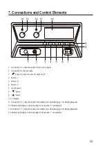
Page 43: ...2 6 Button 3 7 On off switch 8 button 9 button 10 LC display 11 Connection 2 connection socket for soldering iron desoldering gun or soldering tweezers 12 Indicator light lights up when heating for Connection 2 is activated 13 Connection 1 connection socket for soldering iron desoldering gun or soldering tweezers 14 Indicator light lights up when heating for Connection 1 is activated ...

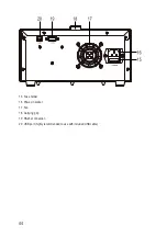
Page 44: ...44 15 Fuse holder 16 Power in socket 17 Fan 18 Carrying grip 19 RS232 connection 20 USB port highly recommended to use with included USB cable ...

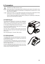
Page 45: ...ion Connect the soldering gun plug with either Channel 1 13 or Channel 2 11 The image on the right shows connection to Channel 2 Insert the correctly aligned plug into the socket then it can be secured using the locking ring Do not use force The vacuum hose is connected to socket 2 using its plug Push the plug as far as it will go in the socket The rubber ring on the plug then ensures a seal Place...

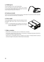
Page 46: ... fixed on the left or right side of the the 4 in 1 rework station using 2 screws Then you can hang up the hot air nozzle The mounting bracket must be mounted in such a way that the hot air nozzle points diagonally upwards when inserted into the mounting bracket f Mains connection Switch off the 4 in 1 rework station move the on off switch to the 0 position Use the mains cable provided to connect t...

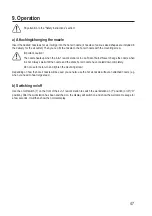
Page 47: ... change the nozzle when it is hot Always wait until the nozzle and the entire hot air nozzle have cooled down completely Do not use force to turn and tighten the mounting screw Depending on how the hot air nozzle will be used you can also use the hot air nozzle without an attached nozzle e g when you need to heat large areas b Switching on off Use the on off switch 7 on the front of the 4 in 1 rew...

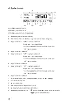
Page 48: ... Display value pre set temperature S E Temperature Sensor Error or no device is connected H E heating unit error F Display for Channel 2 button lock G Display for Channel 3 OFF Channel 3 switched off Display value pre set temperature S E Temperature Sensor Error or no device is connected H E heating unit error H Display for Channel 3 button lock I Fan function symbol symbol is displayed air supply...

Page 49: ...volume First select the desired channel by briefly pressing the 1 2 or 3 button for the associated channel see Section 9 d The selected channel is shown inverted on the display Switch on the selected channel by pressing the corresponding button and holding it down for approx 1 second The display changes from OFF to a temperature display In Channel 1 and 2 mode the warm up process starts in Channel...

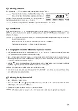
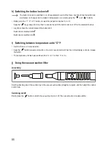
Page 50: ...urrent status of the button lock Button lock is switched off Button lock is switched on i Switching between temperature units C F Switch off the 4 in 1 rework station Keep the button pressed and switch on the 4 in 1 rework station When the normal display is shown release the button The temperature unit has been switched from C to F or from F to C j Using the vacuum suction lifter Assembly Start by...

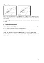
Page 51: ...e desoldering gun has a small hole through which desoldering suction is performed using the vacuum pump in the 4 in 1 rework station Place the soldering tip to the pins of a component so that it encloses these When the solder has become liquid press the finger grip The vacuum pump starts up and the liquid solder will be vacuumed The vacuum pump only starts when the desoldering gun has heated to th...

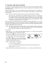
Page 52: ...ing gun to 300 C solder ing iron and soldering tweezers to 200 C the reduction is only possible if the respective channel is set at a higher temperature This not only reduces the power consumption of the 4 in 1 rework station energy savings but also protects the soldering tips during longer work breaks If the channel is in sleep mode SLP display sleep mode can be terminated by briefly pushing the ...

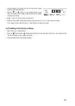
Page 53: ...witched off Briefly press the button corresponding to the selected channel 1 2 or 3 in order to save the setting Then setting mode is exited and the 4 in 1 rework station is ready for use again m Resetting to the factory settings Switch off the 4 in 1 rework station Keep the button and the button pressed at the same time and switch on the 4 in 1 rework station When the normal display is shown rele...

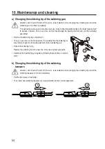
Page 54: ...ng ring completely 1 Then you can remove the front part 2 It is possible that the soldering tip may remain caught on the heating element of the desoldering gun Extract the soldering tip 3 Replace the soldering tip with a new one Only use original spare parts Assemble the desoldering gun again by following these actions in reverse order b Changing the soldering tip of the soldering tweezers Attenti...

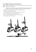
Page 55: ...ever do not use force as this may damage the soldering iron and void the warranty guarantee Insert the tip of the soldering iron as shown in 1 in one of the openings of the holder Slide the soldering tip forwards in the opening 2 Pull out the soldering iron upwards 3 so that the soldering tip remains in the holder Then slide a new tip as far as it will go in the soldering iron 4 The soldering tip ...

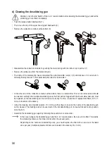
Page 56: ...oved and should be cleaned carefully After multiple desoldering uses the filter will be clogged with the finest solder dust and must be replaced so that desoldering can be carried out correctly For this a selection of replacement filters 14 5 x 3 mm are included in the delivery Using the cleaning wire provided approx 10 cm long with spring at one end the nozzle of the desoldering gun can be cleane...

Page 57: ...s completely cooled down first Shake out the brass wool dispose of solder residue in an environmentally friendly manner g General information Repair work should only be carried out by a specialist The same applies for maintenance procedures other than those described in these operating instructions Before cleaning switch the product off and unplug the mains plug from the mains socket Allow the ent...

Page 58: ...on the size of the nozzle and the distance to the workpiece Calibrate the temperature No temperature or air volume setting possible Switch off the button lock Temperature automatically decreases after a certain time The sleep timer is activated after a certain pre set time tempera ture is turned down Switch off the sleep timer set time to 0 Suction power of the desoldering gun is minimal or the sy...

Page 59: ... with a flat screwdriver Remove the fuse from the fuse holder Perform a continuity test on the fuse e g with an appropriate meter digital multimeter If the fuse is defective replace it with a new fuse of the same type see Technical data at the end of these operating instructions Never use a fuse with other specifications Never bridge a defective fuse This may cause a fire or a fatal electric shock...

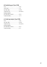
Page 60: ...rature 20 C to 80 C humidity 0 to 80 relative non condensing Dimensions W x H x D 314 x 134 x 309 mm incl holder for the hot air nozzle Weight approx 8 kg incl hot air nozzle holder b Hot air nozzle Type 552B Power 550 W Air pump 25 W Temperature range 150 to 500 C Temperature stability 5 C Air volume 5 23 l min Sound volume 52 dB A Hose length approx 88 cm c Soldering iron Type Y130 Power 130 W O...

Page 61: ...perature range 300 to 500 C Standby temperature when sleep timer is activated 300 C Temperature stability 2 C e Soldering tweezers Type N100 Power 100 W Operating voltage 24 V DC Temperature range 150 to 500 C Standby temperature when sleep timer is activated 200 C Temperature stability 2 C ...

Page 62: ...62 ...

Page 63: ...63 ...

Page 64: ...Publikation entspricht dem technischen Stand bei Drucklegung Copyright 2020 by Conrad Electronic SE This is a publication by Conrad Electronic SE Klaus Conrad Str 1 D 92240 Hirschau www conrad com All rights including translation reserved Reproduction by any method e g photocopy microfilming or the capture in electronic data processing systems require the prior written approval by the editor Repri...

Reviews:

Related manuals for 1933085