background image

Page 8

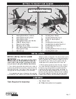
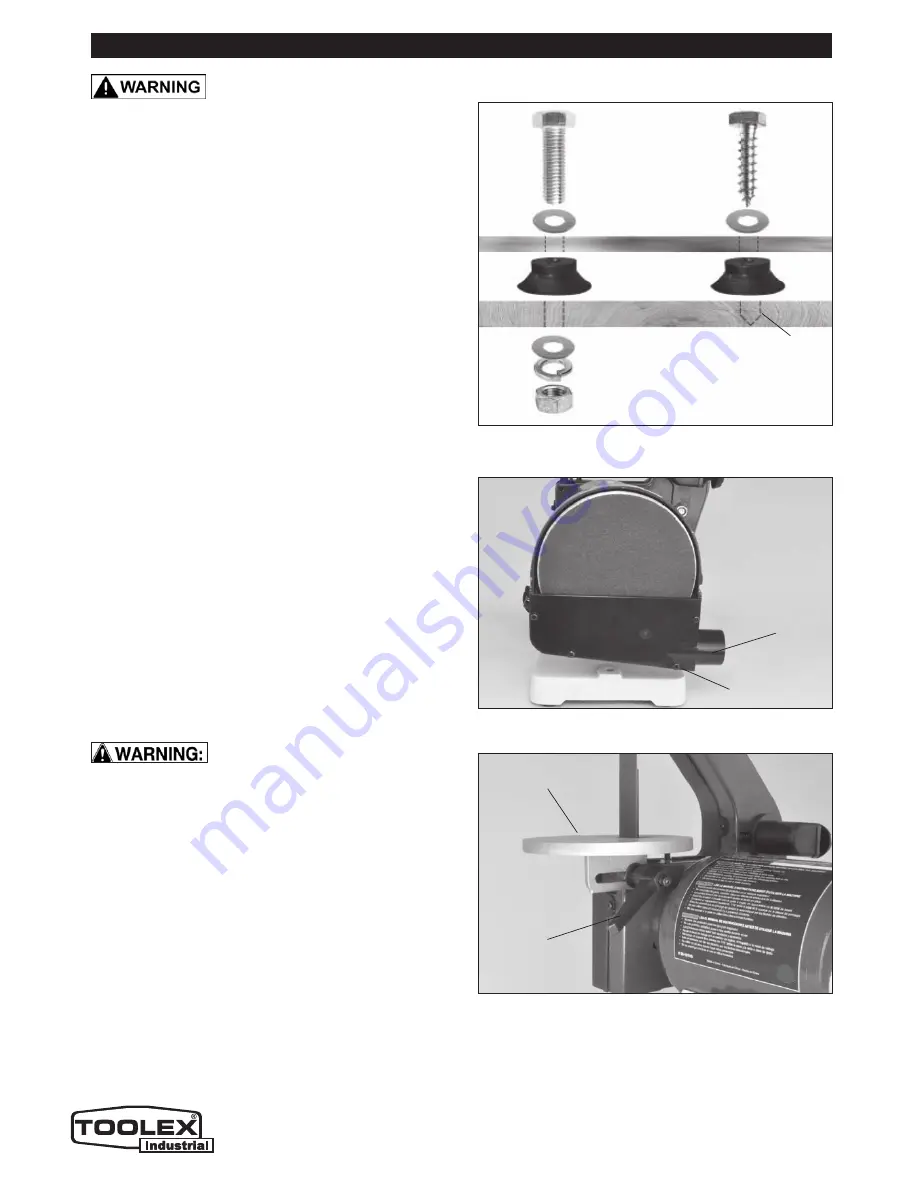
FIG. A

FIG. B

8

ASSEMBLY

MOUNTING THE SANDER TO A WORKBENCH

CAUTION:

 If during operation there is any tendency 

for the sander to tip over, slide or walk on the 

supporting surface, the sander should be properly 

mounted to a workbench or stand, and at a suitable, 

safe height for your sanding work to be carried out.

1. Rubber feet are fastened to this sander prior 

to shipping. They may, or may not, be used when 

attaching the sander to a bench or stand.

2. Position the sander on the workbench.

3. Mark the workbench through the two mounting 

holes located in the left and right sides of the sander 

base (between the holes for rubber feet).

4. Drill holes in the workbench at the 2 marks.

5. Using long bolts, washers, lock-washers and nuts; 

or lag bolts; (fasteners not supplied), secure the 

sander to the workbench. FIG. A.

DUST CHUTE INSTALLATION – DISC SANDER

1. If not already pre-assembled by the factory, fasten 

the sanding disc dust chute and cover (Part #36) to 

the machine using the four Phillips M4 screws and 

washers (#37). FIG. B.

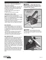
ASSEMBLING THE BELT SANDER TABLE

 When assembling the belt & disc 

sander, ensure the machine is disconnected from any 

power source.

1. Locate the round shaped belt-sanding table (#62).

2. Position the table by threading the belt and plate 

through the table’s slot and square opening.

3. Fasten the table to the frame by using the table-

adjustment knob and 8mm washer (#63, 64). FIG. C.

4. Bring the adjustment knob’s screw through the slot 

in the bracket opening on the underside of the table, 

then into the threaded hole in the frame that houses 

the hex nut (#58). 

5. Fasten the table in place by using the adjustment 

handle to turn its integral screw into the nut.

FIG. C

Lag Bolt

Machine Bolt

Washer

Machine Base

Rubber Foot

Washer

Lock Washer

Nut

Pilot Hole for 

Lag Bolt

Workbench

THE MACHINE MUST NOT BE 

PLUGGED IN AND THE POWER SWITCH MUST BE IN 
THE OFF POSITION UNTIL FULL ASSEMBLY AND ALL 
ADJUSTMENTS ARE COMPLETE.

DISC

SANDER

DUST

CHUTE

SANDING

BELT

TABLE

ADJUSTMENT

KNOB

SCREWS (4)

Note: Not Actual Toolex Product Pictured below

Summary of Contents for 598557

Page 1: ...INSTRUCTION MANUAL 598557 BELT DISC LINISHING SANDER 550WATT MOTOR VARIABLE SPEED 25MM X 762MM BELT SIZE 150MM DISC SIZE CONSUMER SERVICE CENTRE PO BOX 1012 HAMILTON NSW 2303 AUSTRALIA Made in P R C ...

Page 2: ...d to show assembly adjustments and general use Motor 550W S2 30min 230V 50Hz Motor Speed variable 2 000 2 850 RPM Belt Size 25 x 762mm Belt Speed variable 1 900 2 700 SFPM Belt Table Size 146mm Diameter Belt Table Tilt 0 45 Disc Size 150mm Disc Speed variable 2 000 2 850 RPM Disc Table 204x135mm Disc Table Tilt 0 45 Miter Gauge Included Miter Gauge Slot 16x6 5 mm Base Size 170x235mm Dust Ports 2 4...

Page 3: ...your own shadow 8 ALWAYS keep children away All visitors should be kept a safe distance from the work area especially when the machine is being used 9 ALWAYS maintain machine in top condition Keep tools machines clean for the best and safest performance Follow maintenance instructions 10 ALWAYS handle with extreme care and do not carry the tool machine by its electric cable or pull on the cable to...

Page 4: ...VER leave machine running unattended Turn power off Do not leave the machine until it comes to a complete stop 18 NEVER force the machine it will do a better and safer job at the rate for which it was designed 19 NEVER use power tools in damp or wet locations or expose them to rain Do not use in an explosive atmosphere around paint flammable liquids etc Avoid dangerous environments 19 If the tool ...

Page 5: ...length of the cable 9 ALWAYS use a dust extraction device properly connected to the dust extraction port 10 ALWAYS ensure that nails or foreign objects have been removed from a workpiece beforehand Nails etc will destroy the belt or disc 11 NEVER allow the ventilation slots in the motor to become blocked 12 NEVER sand pieces which cannot be held firmly by hand SPECIFIC SAFETY INSTRUCTIONS FOR SAND...

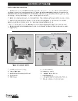
Page 6: ...es with ordinary house hold type grease or spot remover Do not use gasoline paint thinner mineral spirits etc These may damage painted surfaces 4 Apply a coat of paste wax to the table to prevent rust Wipe all parts thoroughly with a clean dry cloth 5 Set packing material and shipping carton aside Do not discard until the machine has been set up and is running properly TABLE OF LOOSE PARTS A Belt ...

Page 7: ...bench to avoid any movement of the machine during use The sander s base has holes for this purpose mounting hardware is not included For portability and secure clamping of the sander to a workbench the machine can be first permanently bolted to a piece of plywood Then the sander can be positioned on your workbench or other solid surface and the plywood can be clamped in place to secure the sander ...

Page 8: ...c dust chute and cover Part 36 to the machine using the four Phillips M4 screws and washers 37 FIG B ASSEMBLING THE BELT SANDER TABLE When assembling the belt disc sander ensure the machine is disconnected from any power source 1 Locate the round shaped belt sanding table 62 2 Position the table by threading the belt and plate through the table s slot and square opening 3 Fasten the table to the f...

Page 9: ...ver knob 63 2 Tilt the table back to the rear as far as possible 3 Using a square or protractor measure the angle of the table against the platen 84 FIG E To adjust the table angle to ensure a 90º angle turn the table s rear adjustment screw 61 as needed and once the 90º is setting is found lock it in place with the hex nut 60 that is under the table forward until it is at the required angle FIG F...

Page 10: ... the old disc paper peel the protective backing from new sanding disc Align perimeter of disc with sanding plate and press disc firmly into position all the way around FIG I FIG G FIG H FIG I ADJUSTMENTS THE MACHINE MUST NOT BE PLUGGED IN AND THE POWER SWITCH MUST BE IN THE OFF POSITION UNTIL FULL ASSEMBLY AND ALL ADJUSTMENTS ARE COMPLETE ADJUSTMENT HANDLE TABLE ANGLE GAUGE DISC TABLE ADJUSTMENTS ...

Page 11: ...port plate that is positioned behind the sanding belt rising from the table level to a point several inches above the table surface Its purpose is to support the belt when sanding The platen should be adjusted so that it is almost touching the back of the sanding belt This can be done by loosening the two hex screws 86 that fasten the bottom of the platen to the sander frame If the platen is out o...

Page 12: ...cannot be turned ON with the key removed Insert the locking key to resume sanding operations GENERAL USAGE FIG N MITER GAUGE A miter gauge is supplied with your sander and can be used on the disc table which has a slot in its head can be set anywhere up to 45º right or left by loosening the lock knob setting the miter gauge head to the desired angle and re tightening the lock knob FIG N DUST CHUTE...

Page 13: ...uses or tripped circuit 1 Motor is overloaded 2 Short circuit in the motor or loose connections 3 Low line voltage 4 Incorrect fuses or circuit break ers in the power line 5 Motor capacitor has failed 6 Belt tension is too tight 1 Reduce the load on the motor 2 Inspect connections on motor for loose or shorted terminals or worn insulation 3 Correct low voltage conditions for ex ample improper exte...

Page 14: ...UVHU JULW VDQGSDSHU 5HGXFH ZRUN SLHFH SUHVVXUH RQ WKH VDQGSDSHU ZKLOH VDQGLQJ R QRW NHHS WKH ZRUN SLHFH VDQG LQJ LQ RQH SODFH IRU WRR ORQJ HHS VDQGLQJ JURRYHV RU VFDUV LQ ZRUN SLHFH 6DQGLQJ EHOW GLVF JULW LV WRR FRDUVH IRU WKH GHVLUHG QLVK RUN SLHFH LV EHLQJ VDQGHG DFURVV WKH JUDLQ 7RR PXFK VDQGLQJ IRUFH RQ WKH ZRUN SLHFH RUN SLHFH KHOG VWLOO DJDLQVW WKH EHOW GLVF IRU WRR ORQJ 8VH D QHU JULW VDQGL...

Page 15: ...Page 15 PARTS DIAGRAM 15 ...

Page 16: ...DEOH RUN WDEOH ORFNLQJ NQRE 3KLOOLSV VFUHZ IODW ZDVKHU 0 HIW HQG FDS DY ZDVKHU DOO EHDULQJ 5 6WDWRU 5RWRU 5LJKW HQG FDS HHGEDFN OLQH 3KLOOLSV VFUHZ 0 HHGEDFN SODWH H VFUHZ 0 5LJKW JXDUG FRYHU RFNLQJ NQRE HOW FRYHU HOW VXSSRUW FRYHU 6DQGLQJ HOW JULW 3KLOOLSV VFUHZ ORFN ZDVKHU 0 ULYH ZKHHO H QXW 0 HOW VXSSRUW H QXW 0 H VFUHZ 0 HOW ZRUN WDEOH RFNLQJ NQRE LJ IODW ZDVKHU 3KLOOLSV VFUHZ 0 H VFUHZ 0 GOHU...

Reviews: