Page 9
9
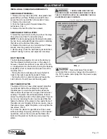
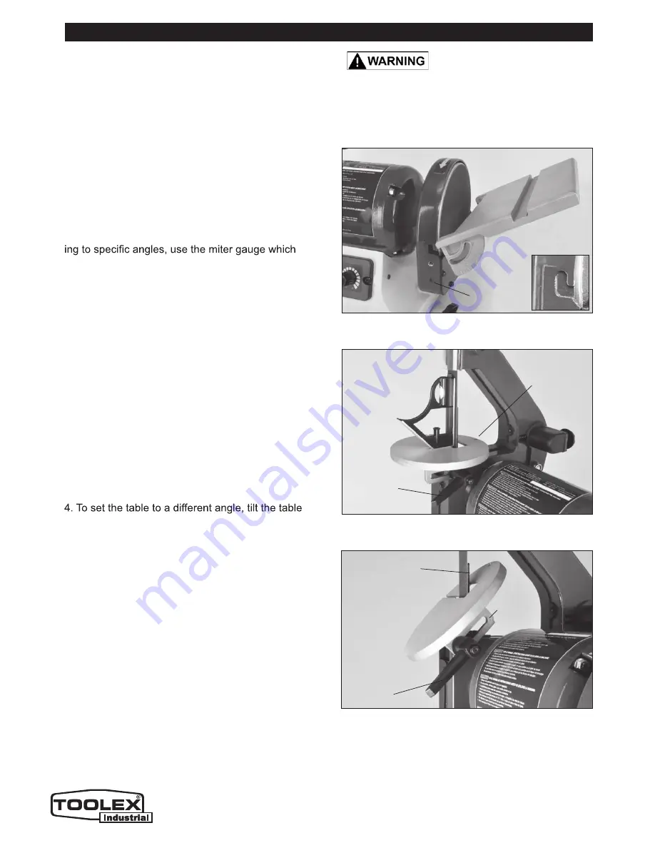
FIG. E
FIG. F
FIG. D
ASSEMBLING THE SANDING DISC TABLE
1. Attach the disc-sanding table (#38) to the sanding
disc guard (#16) by tipping the table up, and slide
the two small nipples extending from the rectangular
mouth of the table, onto the 2 ‘L’ mounting slots in the
sides of the disc sander guide’s frame. FIG. D.
2. Align the two screw holes in the guard with the
arched slots above the angle gauges, so that the
knobs & washers (#39, 95, 94) will travel through the
angle-gauge openings on either side of the disc and
into the mounting holes on the disc sander.
3. Using the disc-table adjustment handles, fasten the
table to the sander.
4. When required for sanding small parts or for sand-
slides in the slot that is in the disc-sanding table.
BELT TABLE ADJUSTMENTS
For most sanding operations, the table will likely
remain at a 90º angle to the belt. A positive stop is
provided with your sander to ensure fast positioning
of the table at 90 degrees to the belt. To ensure and
check the positive-stop 90º angle, proceed as follows:
1. Loosen the table-locking lever / knob (#63).
2. Tilt the table back to the rear as far as possible.
3. Using a square or protractor, measure the angle of
the table against the platen (#84). FIG. E. To adjust
the table angle to ensure a 90º angle, turn the table’s
rear adjustment screw (#61) as needed, and once the
90º is setting is found, lock it in place with the hex nut
(#60), that is under the table.
forward until it is at the required angle. FIG. F.
5. Tighten the table-locking lever to lock the table in
position for sanding.
NOTE:
To get the full range of table angling, the
table-locking handle lever must be very loose, so that
it slides along the slot in the table bracket. The table
can then be moved back to get maximum angles.
ASSEMBLY & ADJUSTMENTS
THE MACHINE MUST NOT BE
PLUGGED IN AND THE POWER SWITCH MUST BE
IN THE OFF POSITION UNTIL FULL ASSEMBLY AND
ALL ADJUSTMENTS ARE COMPLETE.
INSTALLING & CHANGING SANDING DISCS
DISC TABLE ADJUSTMENTS
1. To check the trueness of the 90º angle of the
disc-sanding table, place a square or other measur-
ing device on the table with the other end against the
sanding disc. FIG. G.
‘L’ SLOT
TABLE TILT
ANGLE
INDICATOR
TABLE
LOCKING
LEVER
TABLE
ADJUSTING
SCREW
TABLE
LOCKING
LEVER
PLATEN
BEHIND
THE BELT
BRACKET
& SLOT
Note: Not Actual Toolex Product Pictured below
Summary of Contents for 598557
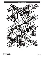
Page 15: ...Page 15 PARTS DIAGRAM 15 ...


