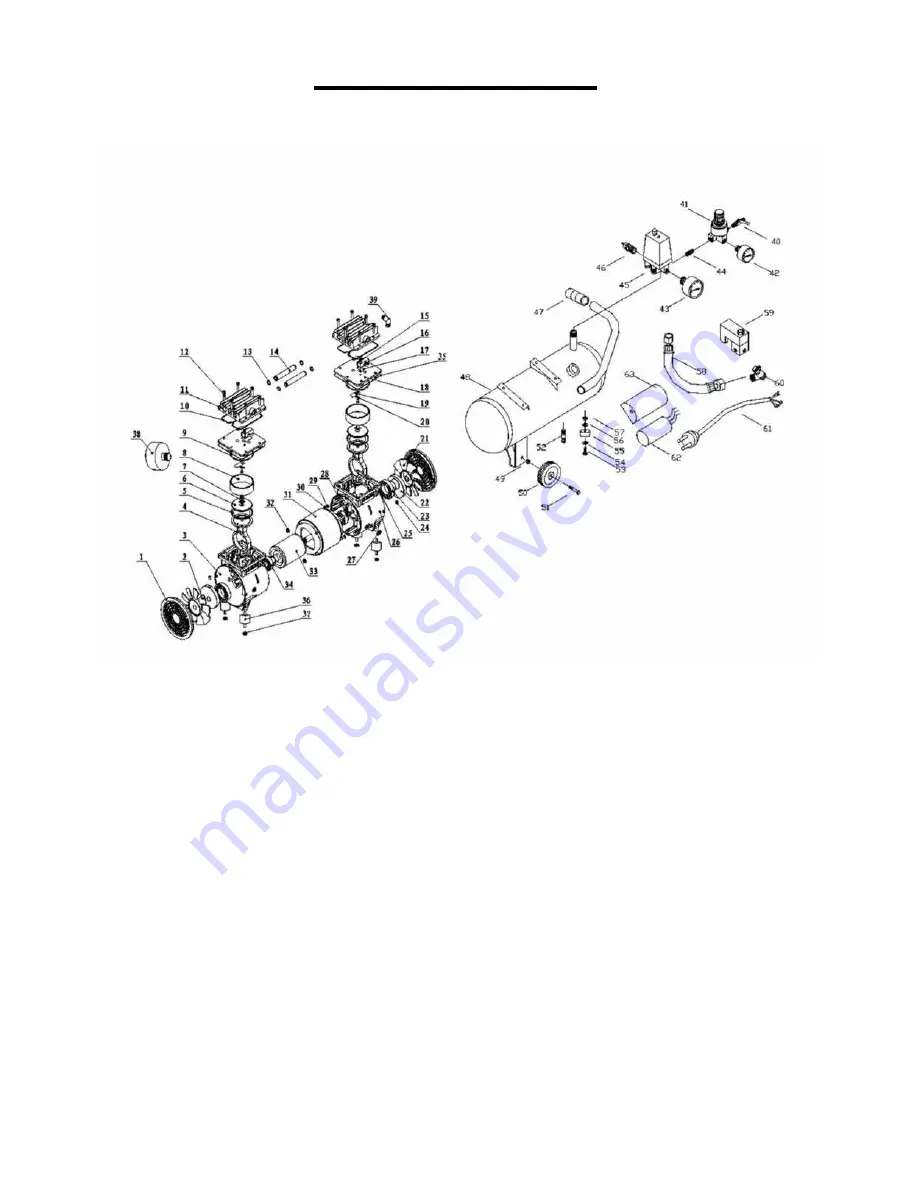
PARTS DIAGRAM
1. Cover
2. Left Fan
3. Left Crankcase
4. Connecting Rod
5. Piston Cup
6. Binder Plate
7. Con Rod Bolt
8. Cylinder
9. Cylinder Seal
10. Head Seal
11. Cylinder Head
12. Head Bolt
13. ‘O’ Ring
14. Transfer Pipe
15. Valve Plate Bolt
16. Valve Block
17. Reed Valve
18. Reed Valve
19. Valve Plate
20. Washer
21. Right Fan
22. Shaft Seal
23. Bearing 6908-2z
24. Bearing Bolt
25. Bearing Bolt
26. Right Crankcase
27. Protection Ring
28. Assembly Bolt
29. Assembly Bolt
30. Spring Washer
31. Stator
32. Assembly Nut
33. Rotor
34. Bearing 6203-2z
35. Adjusting Washer
36. Rubber Mount
37. Spring Washer
38. Air Filter
39. Elbow
40. Deflating Tap
41. Regulator
42. Outlet Pressure gauge
43. Tank Pressure gauge
44. Connector
45. Pressure Switch
46. Safety Valve
47. Handle
48. Tank
49. Wheel Nut
50. Wheel
51. Bolt (Axle)
52. Tank Drain Cock
53. Bolt
54. Washer
55. Cushion Foot
56. Washer
57. Nut
58. Pipe
59. Actuated Valve
60. Non Return Valve
61. Plug and Lead
62. Capacitor
63. Capacitor cover
4.


