background image

Customer Helpline

 1300 889 028

13

Operating Instructions

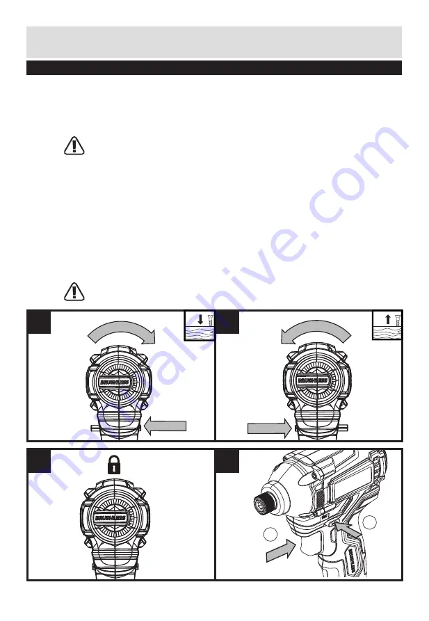
4. REVERSIBLE (SEE FIG E1, E2)

Forward rotating: push the forward/reverse rotation control to the left (the drill points 
away from you). It is used for drilling and screw driving.
Reverse rotation: push the forward/reverse rotation control to the right (the drill points 
away from you). It is used for remove screws or release a jammed drill bit.

WARNING: Never change the direction of rotation when the chuck is rotating, 
wait until it has stopped!

                                              
5. SWITCH LOCK (SEE FIG F)

The switch trigger can be locked in the OFF position. This helps to reduce the possibility 
of accidental starting when not in use. To lock the switch trigger, place the rotation 
control in the center position.

6. ON/OFF SWITCH (SEE FIG G)

Depress to start and release to stop your driver. 
The On/Off Switch is fitted with a brake function which stops your chuck immediately 
when you quickly release the switch. 
It is also a variable speed switch that delivers higher speed and torque with increased 
trigger pressure. Speed is controlled by the amount of On/Off switch depression. 

WARNING: 

Do not operate for long periods at low speed because excess heat will 

be produced internally.

E1

F

E2

G

1

2

Summary of Contents for 600277

Page 1: ...r impact driver These instructions contain important information that will help you get the best from your impact driver ensuring it remains safe to operate If you need help or have damaged or missing...

Page 2: ...Customer Helpline 1300 889 028 2 Contents Safety Information 3 In The Box 9 Accessories 9 Operating Instructions 10 Maintenance 15 Technical Data 16...

Page 3: ...g to separate collection for all battery packs and battery pack It will then be recycled or dismantled in order to reduce the impact on the environment Battery packs can be hazardous for the environme...

Page 4: ...entering a power tool will increase the risk of electric shock d Do not abuse the cord Never use the cord for carrying pulling or unplugging the power tool Keep cord away from heat oil sharp edges or...

Page 5: ...k of starting the power tool accidentally d Store idle power tools out of the reach of children and do not allow persons unfamiliar with the power tool or these instructions to operate the power tool...

Page 6: ...f Do not expose a battery pack or tool to fire or excessive temperature Exposure to fire or temperature above 130 C may cause explosion g Follow all charging instructions and do not charge the battery...

Page 7: ...ediately if a cell or battery pack has been swallowed g Keep battery pack clean and dry h Wipe the battery pack terminals with a clean dry cloth if they become dirty i Battery pack needs to be charged...

Page 8: ...charger is matching the local AC supply 6 The charging device must be protected from moisture 7 Do not use the charging device outdoors 8 Do not short out the contacts of battery or charger 9 Respect...

Page 9: ...6 7 9 8 4 Forward Reverse Rotating Control On Off Switch Soft Grip Handle Battery Pack Battery Pack Release Button Belt Clip Sight Light Chuck Battery Capacity Indicator 2 3 4 6 1 5 7 8 9 Accessories...

Page 10: ...attery to cool down before recharging d Please charge the battery to reach full or no less than half charge before storage If the tool will not be used for long periods of time charge the battery ever...

Page 11: ...termine if the charger is OK If the new battery charges correctly then the original pack is defective and should be returned to a service center or recycling service center If the new battery pack dis...

Page 12: ...ack onto the tool with sufficient force until it clicks into position 2 INSERTING A BIT HOLDER SOCKET OR SCREWDRIVER BIT SEE FIG C Pull the Chuck Sleeve b forward Fully insert the desired bit into the...

Page 13: ...LOCK SEE FIG F The switch trigger can be locked in the OFF position This helps to reduce the possibility of accidental starting when not in use To lock the switch trigger place the rotation control in...

Page 14: ...e left in the battery Fuel Gauge Capacity 3 lights 70 2 lights 40 70 1 light 40 9 BELT CLIP SEE FIG H1 H2 Screw the Belt Clip 6 on the tool with the screw provided in the plastic bag The Belt Clip can...

Page 15: ...ool requires no additional lubrication or maintenance There are no user serviceable parts in your power tool Never use water or chemical cleaners to clean your power tool Wipe clean with a dry cloth A...

Page 16: ...e QLD 4500 Australia FREE CALL 1300 889 028 EMAIL salesau positecgroup com Technical Data Technical Data Table CID18BWG CID18BWG 9 Rated voltage 18V No load speed 0 3200 min Impact rate 0 3600 bpm Max...

Reviews: