background image

-

cally.

-

cally.

to

:

side of the table to prevent interfering with the movement of the cutting head.
Always check before making the cut if there is any potential interference from the 
clamp or any other part of the machine

.

Even though the angles are marked on the machine, it is always a good 
idea to check them by making a trial cut. See Aligning Miter and Bevel 
on next page. 

-

soap and a damp (not wet) cloth. 

lower blade

6

Summary of Contents for 240-2093

Page 1: ...Operator s Manual...

Page 2: ...t expose tools to the rain Keep the work area away from the work area Don t let them handle machines tools or extension cords electric shock if you contact a live wire 2 immediately wet conditions can...

Page 3: ...the switch is in the posi if the tool would accidentally start any tool when you are tired center Don t use the tool if switch does not turn it on and off properly parts shock or injury injury in use...

Page 4: ...Speed 5000 RPM No Load Speed Blade Diameter 10 40 tooth carbide tipped Arbor Size 5 8 Positive Miter Stops 0 15 22 5 30 45 degree Miter Angle 45 degree Left 45 degree Right Bevel cuts up to 45 degree...

Page 5: ...ched screws are fastened and all adjusting keys and wrenches are removed 2 Put on the dust bag 6 on page 4 and install the table extension 13 on page 4 with the screw provided 3 Connect the saw to pow...

Page 6: ...k before making the cut if there is any potential interference from the clamp or any other part of the machine Even though the angles are marked on the machine it is always a good idea to check them b...

Page 7: ...needle Bevel Scale Make sure the Fence is perpendicular at a 90 angle to the Saw Blade using carpenter square can be purchased at any hardware store and comes in various sizes using a small using a sm...

Page 8: ...w saw blade the direction arrows on the blade should correspond with the arrow on the upper guard A Upper blade guard B Lower blade guard C Saw teeth pointing down See Figure 1 See Figure 2 FIG 2 FIG...

Page 9: ...nting downward Replace outer flange Tighten spindle bolt securely using the blade wrench and tightening counterclockwise Rotate lower blade guard back into place replace any screws that were removed t...

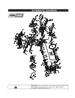
Page 10: ...Please refer to the schematic drawing on page 11 10...

Page 11: ...Repairs should be made by an authorized repair center Do not this power tool Contact at for questions regarding this power tool 1 866 915 8626 open or disassemble 11...

Page 12: ...nd you may have other rights which vary from state to state Be careful tools are dangerous if improperly used or maintained Seller s employees are not qualified to advise you on the use of this Mercha...

Reviews: