SPECIFICATIONS
120 volts AC, 7.2 Amps
Sanding Belt size: 3” x 21”
Variable speed dial: 393-1,240 SFPM
Padded handle insert
Dust bag
Double Insulated
C-UL US listed
APPLICATIONS
Sanding of wood and other materials
Paint and rust removal
SWITCH
CAUTION:
A sanding belt may have been installed at the factory and the belt
tracking may not be set correctly. Follow steps 5 & 6 in REMOVING, INSTALLING,
in REMOVING, INSTALLING, and ADJUSTING BELTS, below.
CAUTION:
Before plugging the tool in, squeeze the trigger once and release it to
be sure the trigger is “Off” and not locked “On”.
CAUTION:
Be sure the belt is not in contact with the workpiece when starting the
tool.
Lift the tool off the workpiece, with one hand holding the handle at the front and
the other grasping the handle at the rear.
Squeeze the trigger in the rear handle with your index finger to start the tool.
Release it to stop.
To lock the trigger in the “On” position, press the small round button on the
left side of the rear handle with your thumb at the same time as the trigger is
squeezed fully with your index finge
r.
REMOVING, INSTALLING, and ADJUSTING BELTS
WARNING:
To prevent injury, always switch off and disconnect the tool from power
source before removing or installing the sanding belt.
1. Pull the belt tension lever from the right side of the sander and move it towards
the front of the machine. This pulls the idler (front) pulley back. The old belt
can be slid easily off the pulleys.
2. Check that the new 3”x 21” belt’s direction arrow (usually printed on the inside
fabric backing of the belt) matches the direction of belt travel on the tool. The
belt will move from the front to the back on the bottom, exposed surface of the
tool. A
belt installed backwards will not work as efficiently and have a short
-
ened life.
3. Slide a 3”x 21” abrasive belt over the front and back pulleys and line it up so
that it is as close to centered, with as little overhang as possible on both sides
at both the front idler pulley and at the back drive pulley.
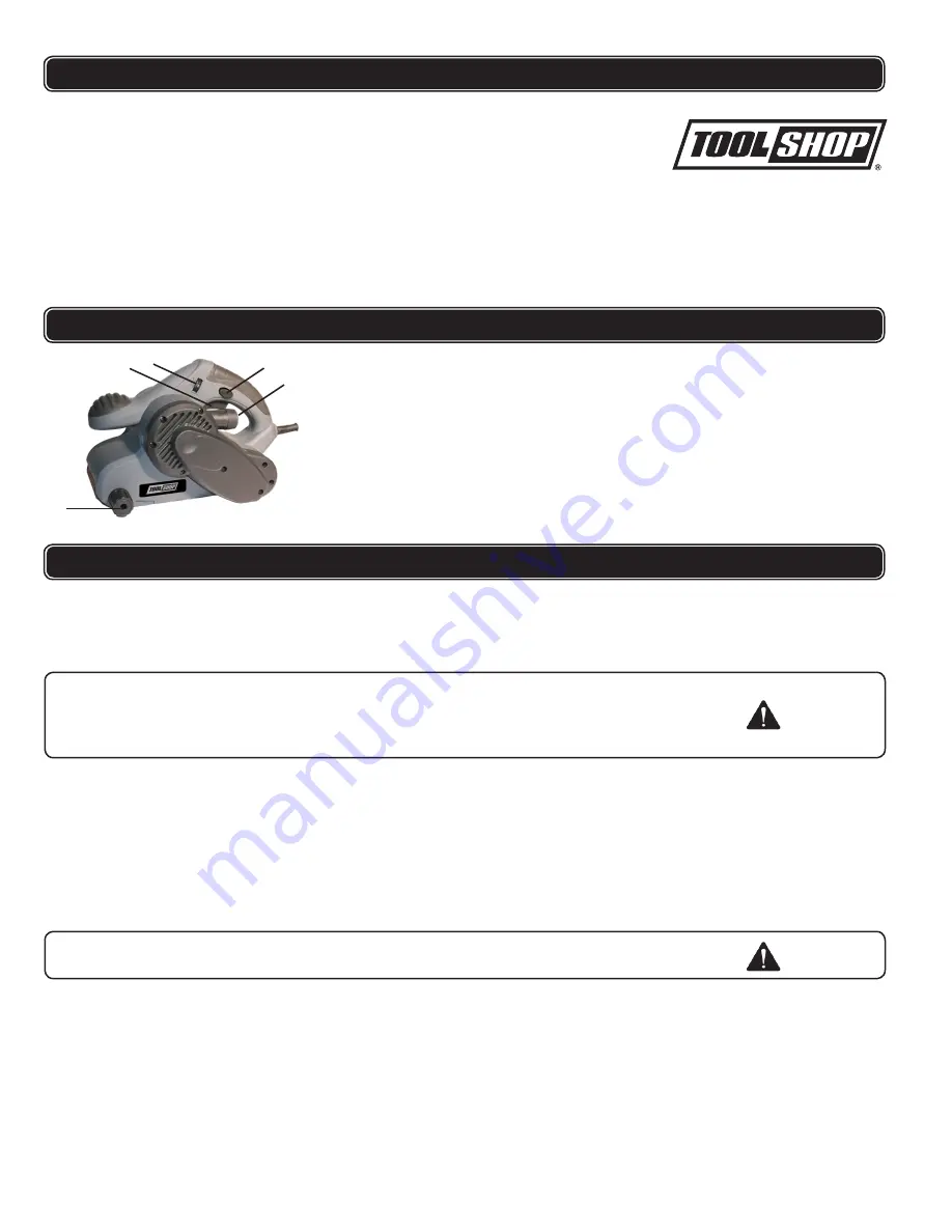
A. ON - OFF Switch
B. Lock on button
C.
D.
Dust extraction outlet
E.
Belt tracking knob
Variable speed switch
FUNCTION DESCRIPTION
OPERATING PROCEDURES
A
B
C
D
E
4


