background image


16 


WARNING:

 When servicing, use only original equipment replacement parts. The use of any 

other parts may create a safety hazard or cause damage to the sander. 


Any attempt to repair or replace electrical parts on this sander may create a safety hazard unless 

repairs are performed by a qualified technician. For more information, call the Toll-free Helpline, at 1-

866-349-8665. 


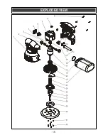
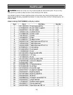
Always order by PART NUMBER, not by key number. 


Key # 

Part # 

Part Name 

Quantity 

3011060024  Housing assembly 

3150060005  Brush holder support 

2030070001  Brush holder 

1230010120  Carbon brush 

3140080036  Switch cover 

1061250001  Switch 

1020060021  Stator 

3140060001  Rubber buffer 

4030010106  Tapping screw ST3.9*19 

10 

1250010002  Tapping screw 

11 

4030010099  Tapping screw ST3.9*14 

12 

3150020001  Cord clamp 

13 

3140010054  Cord guard 

14 

1190030006  Cord 

15 

4010010053  Bearing 607 2RS 

16 

3140020023  "O" ring 

17 

1010060020  Rotor 

18 

4010010054  Bearing 6000 2RS 

19 

3180040048  Vacuum adaptor 

20 

3150010087  Fan 

21 

2030030196  Counterbalance 

22 

6150030048  Dust Bag 

23 

2010130030  Eccentric seat 

24 

2030170007  Dustproof washer 

25 

2020130001  Bearing block 

26 

4010010084  Bearing 6000RS 

27 

2030020033  Washer 

28 

4020080004  Hexagon screw M5*16 

29 

2030160007  Large washer 

30 

1150020007  Bubber backing pad 

31 

4040030011  Spring washer 5 

32 

4020010081  Special screw M5*14 

PARTS LIST 

Summary of Contents for 241-9942

Page 1: ...ECIFICATIONS Rating 120V 60Hz AC Amperes 2 0 AMP No load speed 12 000 OPM Disc diameter 5 Weight 3 lb 6 oz 1 53 kg Need Assistance Call us on our toll free customer support line 1 866 349 8665 Technic...

Page 2: ...Personal safety 5 6 Power tool use and care 6 Service 6 Specific safety rules 7 Extension cord safety 8 Symbols 9 Know your sander 10 Assembly and operating 11 13 Installing a sanding disc 11 ON OFF s...

Page 3: ...aring in this manual are not meant to cover all possible situations It must be understood that common sense and caution are factors which cannot be built into the product ALWAYS WEAR EYE PROTECTION TH...

Page 4: ...r The level of risk from exposure to these chemicals varies according to how often this type of work is performed In order to reduce exposure to these chemicals work in a well ventilated area and use...

Page 5: ...ctric shock If operating a power tool in a damp location is unavoidable use a residual current device RCD protected supply Use of a ground fault circuit interrupter GFCI reduces the risk of electric s...

Page 6: ...perate the power tool Power tools are dangerous in the hands of untrained users Maintain power tools Check for misalignment or binding of moving parts breakage of parts and any other condition that ma...

Page 7: ...G Always use hearing protection when sanding particularly during extended periods of operation WARNING Always unplug the tool from the power source before changing the sanding disc or buffing pad and...

Page 8: ...separate electrical circuit for your power tools This circuit must not be less than 14 gauge wire and should be protected with either a 15 AMP time delayed fuse or circuit breaker Before connecting t...

Page 9: ...ase alternating current Three phase alternating current with neutral Direct current No load speed Alternating or direct current Class II construction Splash proof construction Watertight construction...

Page 10: ...10 KNOW YOUR SANDER Dust Bag Assembly Palm Grip 8 Hole Hook and Loop sanding base Motor vents Hook loop fastening system ON OFF switch Motor vents 3 sanding discs 1 x 60 grit 1 x 80 grit 1 x 120 grit...

Page 11: ...nd side of the switch 1 Fig 3 To turn the switch OFF press the right hand side of the switch 2 CONNECTING THE DUST BAG ASSEMBLY TO THE SANDER 1 Slide the dust bag connector 1 into the dust port 2 in t...

Page 12: ...Where the sanding disc grits are shown numerically higher numbers indicate finer grit and lower numbers indicate coarser grit If the surface is rough start with a coarse grit and sand until the surfa...

Page 13: ...r the cooling vents 2 with your hand Covering the cooling vents could cause the motor to be damaged by overheating CLEAN THE DUST BOX OFTEN Clean the dust bag often It will be more efficient when it i...

Page 14: ...elerated wear and possible premature failure when they are used on fiberglass boats and sports cars wallboard spackling compounds or plaster The chips and grindings from these materials are highly abr...

Page 15: ...15 EXPLODED VIEW...

Page 16: ...1061250001 Switch 1 7 1020060021 Stator 1 8 3140060001 Rubber buffer 2 9 4030010106 Tapping screw ST3 9 19 5 10 1250010002 Tapping screw 1 11 4030010099 Tapping screw ST3 9 14 2 12 3150020001 Cord cl...

Page 17: ...l rights and you may have other rights which vary from state to state Be careful tools are dangerous if improperly used or maintained Seller s employees are not qualified to advise you on the use of t...

Reviews: